00198661-02_UM_SX12-V3_EN.pdf - 第222页
4 Setting up and commissioning Instruction manual SIPLACE SX1/SX 2 Edition V2 and V3 4.4 Adjusting the component trolley to the PCB conveyor height F rom software version SC.713.1 Edition 12/2020 222 4.4.1 W arning instr…
Instruction manual SIPLACE SX1/SX2 Edition V2 and V3 4 Setting up and commissioning
From software version SC.713.1 Edition 12/2020 4.4 Adjusting the component trolley to the PCB conveyor height
221
4.4 Adjusting the component trolley to the PCB conveyor
height
The component trolley can be easily and quickly adjusted to the following PCB conveyor heights:
900 mm
4
930 mm (standard height) 4
950 mm (SMEMA height) 4
4
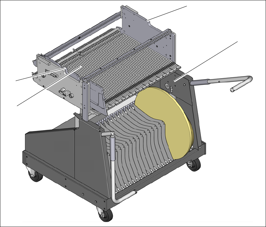
Fig. 4.4 - 1 Component trolley 60
(1) Holes for the transport heights of 900, 930 and 950 mm.
(2) Changeover table
(3) M8 holes for fixing the mounting device
(1)
(2)
(3)
(3)
4 Setting up and commissioning Instruction manual SIPLACE SX1/SX2 Edition V2 and V3
4.4 Adjusting the component trolley to the PCB conveyor height From software version SC.713.1 Edition 12/2020
222
4.4.1 Warning instructions
4
4.4.2 Tools and equipment
You will need the following tools and equipment to adjust the height of the component trolley:
– Mounting device (item no. 03015976-xx)
– Lifting device for raising the component trolley table, carrying capacity at least 80 kg
4.4.3 Changing the component trolley height
4
Fix the fit-up aid to the changeover table with the two M8 x 50 hexagon socket head screws.
There are two different holes available for the changeover table 60 and the changeover table
30.
Hook the leverage device into the eyelet.
Loosen the fastening screws and lift the changeover table into the required position.
Fit and tighten the fastening screws.
WARNING
Adjustment of component trolley height by certified persons!
Only ASM engineers or qualified personnel are permitted to adjust the component trolley
height.
Always follow the applicable accident prevention regulations.
Remove all the feeder modules from the changeover table, if you want to adjust the
height of the changeover table.
WARNING
Risk of damage!
Lifting and lowering the changeover table can lead to deformation of it.
Remove all the feeder modules from the changeover table.
Fit the mounting device to the changeover table in order to adjust the height.
Instruction manual SIPLACE SX1/SX2 Edition V2 and V3 4 Setting up and commissioning
From software version SC.713.1 Edition 12/2020 4.5 Adjusting the empty tape duct to the component height
223
4.5 Adjusting the empty tape duct to the component
height
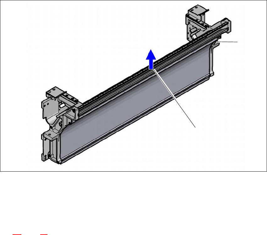
If feeder modules which use tapes with a pocket height of > 12 mm are used, remove the sepa-
rating plate
(1).
4
(1) separating plate for tapes > 12 mm, removable
(2) Fastening screws
Switch the placement machine off at the main switch to remove the dividing plate.
Disconnect the placement machine from the power and compressed air supply.
Lock the placement machine to prevent unauthorized reactivation, as described in section
2.9
, page 97.
Vent the compressed air lines and the tape cutter:
If there is a vent valve (only SIPLACE SX1/SX2 V3), open this valve.
If there is no vent valve (SIPLACE SX1/SX2 V2 and older versions), pull off one of the
small hoses on the T-section of the tape cutter.
Wait until the operating pressure for the tape cutter has dropped to 0 MPa.
Loosen the fastening screws.
Pull out the separating plate.
(1)
(2)