00198661-02_UM_SX12-V3_EN.pdf - 第82页
2 Operational safety Instruction manual SIPLACE SX1/SX2 Edition V2 and V3 2.6 Safety features From software version SC.713.1 Edition 12/202 0 82 2.6.3.2 Position of protective switc hes on the placement machine 2 Fig. 2.…
Instruction manual SIPLACE SX1/SX2 Edition V2 and V3 2 Operational safety
From software version SC.713.1 Edition 12/2020 2.6 Safety features
81
2
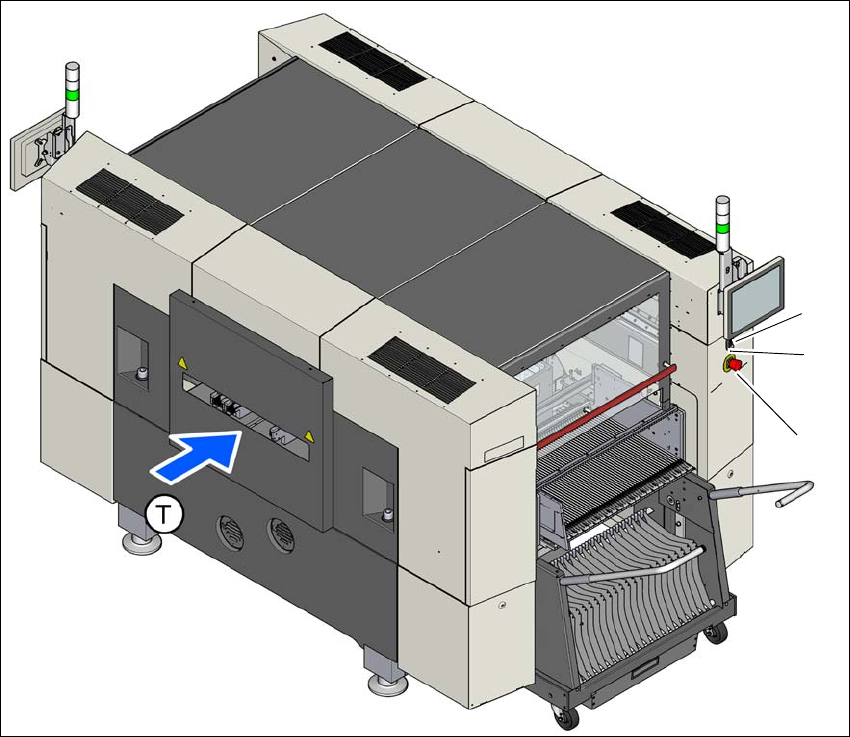
Fig. 2.6 - 5 Position of switches and buttons - View of the PCB input side
(1) EMERGENCY STOP button
(2) Start button (white)
(3) Stop button (black)
(T) PCB transport direction
(2)
(1)
(3)
2 Operational safety Instruction manual SIPLACE SX1/SX2 Edition V2 and V3
2.6 Safety features From software version SC.713.1 Edition 12/2020
82
2.6.3.2 Position of protective switches on the placement machine
2
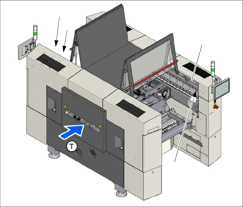
Fig. 2.6 - 6 Position of protective switches on the placement machine
(1) Protective cover switch, location 1
(2) Protective cover switch, location 2
(3) Protective switch for bumper detection
(T) PCB transport direction
(2)
(1)
(3)
(3)

Instruction manual SIPLACE SX1/SX2 Edition V2 and V3 2 Operational safety
From software version SC.713.1 Edition 12/2020 2.6 Safety features
83
2.6.3.3 Description of functions
Main switch in OFF position (see item 1 in fig.
2.6 - 4, page 80) 2
The main power switch disconnects the three phases L1, L2, and L3 from the power supply.
2
2
Main switch in ON position 2
When the main switch is switched to ON, the mains voltage is switched through to the power sup-
ply unit and all AC/DC converters are addressed.
The control computer will start and all supply voltages will be made available internally. The inter-
mediate circuit voltages for the gantry axes (300 V-) and star axes (160 V-) plus the supply voltage
for the conveyor drives are also connected via the start button for safety purposes.
DANGER
Lethal voltages!
Incorrect handling of this placement machine can therefore result in death or severe injury
or considerable damage to equipment.
The following components still carry potentially lethal voltages even if the main power
switch is switched off:
– Cable connection terminals L1, L2, and L3 of the S1 main power switch
– Main input terminal X94
– Connection terminal X98
– The color of all individual wires, which still carry electricity, even if the main power
switch is switched off, is orange.
Always follow the applicable accident prevention and DIN regulations (particularly EN
60204, part 1 or IEC 60204, part 1) and the applicable regulations in your own coun-
try.
The safety door to the power supply must ONLY be opened by appropriately qualified
and trained personnel.
DANGER
Due to the use of energy storing devices in the
power supply unit hazardous voltages are
still present in parts of the power supply unit for approx. 5 minutes after turning off the
main switch and after disconnecting from the mains power supply.