00198661-02_UM_SX12-V3_EN.pdf - 第85页
Instruction manual SIPLACE SX1/SX2 Edition V2 and V3 2 Operation al safety From software version SC.713.1 Edition 12/2020 2.6 Safety features 85 Protective cover switch location 1 and location 2 (item 1 and 2 in fig. 2.6…

2 Operational safety Instruction manual SIPLACE SX1/SX2 Edition V2 and V3
2.6 Safety features From software version SC.713.1 Edition 12/2020
84
Start button (item 2 in fig. 2.6 - 4, page 80 and item 2 in fig. 2.6 - 5, page 81) 2
After switching on the main power switch and starting the control program, you will be prompted
to press the start button in order to start the placement machine for placement jobs. The same
prompt will appear after you have opened the protective covers or pressed the EMERGENCY
STOP button and then want to recommence placement operations with the placement machine.
Press the start button for at least 200 ms, up to a maximum of 1500 ms, and then let go. The
placement machine will be switched on when you let go of the button and the protective cov-
ers will be mechanically held closed.
Stop button (black) (item 3 in fig. 2.6 - 4, page 80 and item 3 in fig. 2.6 - 5, page 81) 2
These buttons are used to stop the placement machine.
Component counter 2
The number of placed components (component counter) can be read on the station software. For
more information, refer to the Online Help.
EMERGENCY STOP button with forced locking (item 4 in fig. 2.6 - 4, page 80 and item 1 in fig.
2.6 - 5, page 81) 2
The EMERGENCY STOP button is red and latches in the ON position when pressed. When you
press the EMERGENCY STOP button, the switching contact of the EMERGENCY STOP circuit
opens and the safety cutoff (CBS) trips. The intermediate circuit voltage (300 VDC) for the gantry
axes and the intermediate circuit voltage (160 VDC) for the star axes is switched off. The servo
amplifiers for the DP and Z axes are still supplied with 42 VDC. The signaling contact of the
EMERGENCY STOP button opens and the message "EMERGENCY STOP pressed" appears on
the screen. The following modules are deactivated:
– PCB conveyor
– PCB clamping
– Width adjustment
– PCB stopper
– Compressed air supply for empty tape cutter
2
PLEASE NOTE
Placement will be interrupted and can then either be continued or canceled, once the
placement machine is working correctly again.

Instruction manual SIPLACE SX1/SX2 Edition V2 and V3 2 Operational safety
From software version SC.713.1 Edition 12/2020 2.6 Safety features
85
Protective cover switch location 1 and location 2 (item 1 and 2 in fig. 2.6 - 6, page 82) 2
These switches check whether the protective covers are closed. When they are closed, the
EMERGENCY STOP contact, the signaling contact and also the EMERGENCY STOP circuit are
closed. If one of the covers is opened, the EMERGENCY STOP contact and the signaling contact
will open. Individual components are disabled or remain enabled (see fig. 2.6 - 8
, page 89 ).
Protective switch for bumper detection (item 3 in fig. 2.6 - 6, page 82) 2
In SIPLACE SX1/SX2 machines, this switch checks whether at least one bumper is present. This
ensures that at least one bumper has been installed again after gantry replacement.
2 Operational safety Instruction manual SIPLACE SX1/SX2 Edition V2 and V3
2.6 Safety features From software version SC.713.1 Edition 12/2020
86
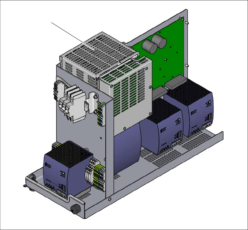
2.6.4 Safety cutoff (CSB)
2
Fig. 2.6 - 7 Position of the safety cutoff (CSB)
2
(1) Safety cutoff (CSB)
(1)