00198661-02_UM_SX12-V3_EN.pdf - 第157页
Instruction manual SIPLACE SX1/SX2 Edition V2 and V3 3 Technical data and assemblies From software version SC.713.1 Edition 12/2020 3.10 X feeder modu les 157 3.10.1.4 Design of the SIPLACE SmartFeeder Xi 3 The following…
3 Technical data and assemblies Instruction manual SIPLACE SX1/SX2 Edition V2 and V3
3.10 X feeder modules From software version SC.713.1 Edition 12/2020
156
3.10.1.3 Design of the SIPLACE SmartFeeder X
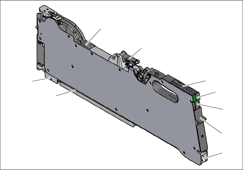
The following diagram shows the design of the SIPLACE SmartFeeder X.
3
Fig. 3.10 - 1 SIPLACE SmartFeeder X
(1) Entry to the tape guide channel with tape spring
(2) Flap on cover foil container
(3) Removal handle, engaged
(4) Status display
(5) Operating panel - LED display
(6) Foil rocker
(7) Tape guide channel outlet
(8) Front slider guide
(9) Back slider guide
(1)
(2)
(3)
(4)
(5)
(6)
(
8)
(
9)
(7)
Instruction manual SIPLACE SX1/SX2 Edition V2 and V3 3 Technical data and assemblies
From software version SC.713.1 Edition 12/2020 3.10 X feeder modules
157
3.10.1.4 Design of the SIPLACE SmartFeeder Xi
3
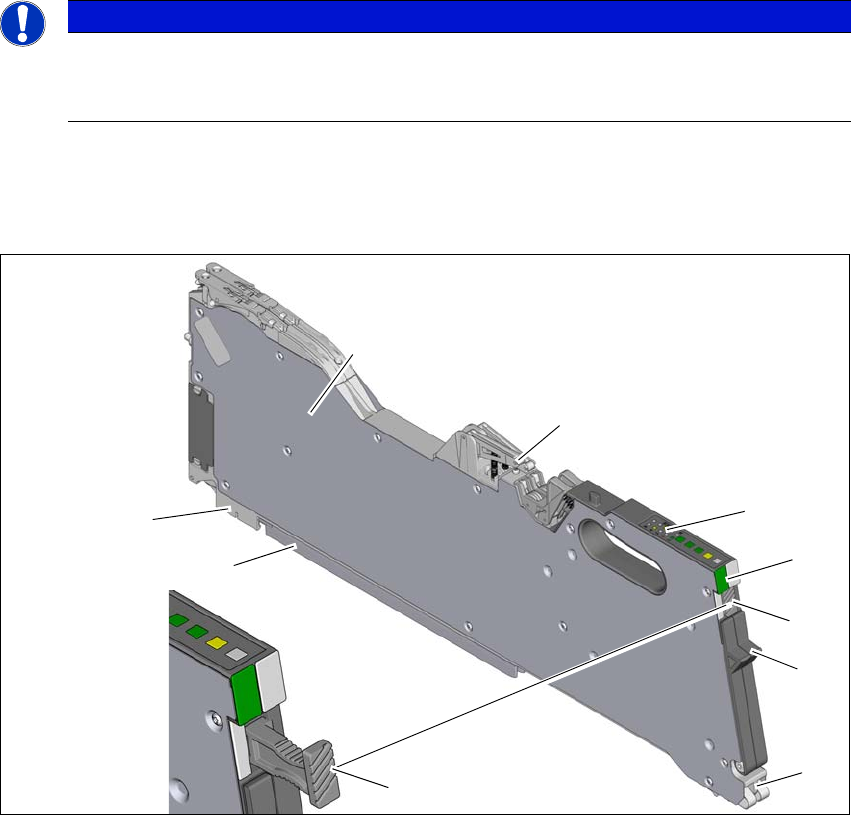
The following diagram shows the design of the SIPLACE SmartFeeder Xi, using the example of
the SIPLACE SmartFeeder 2 x 8 mm Xi. The SIPLACE SmartFeeder Xi can be recognized by its
slanted and grooved surface on the removal handle.
3
Fig. 3.10 - 2 SIPLACE SmartFeeder 2 x 8 mm Xi
(1) Entry to the tape guide channel with tape spring
(2) Flap on cover foil container
(3) Removal handle, docked (grooved surface)
(4) Status display
(5) Operating panel - LED display
(6) Foil rocker
(7) Tape guide channel outlet
(8) Front slider guide
(9) Back slider guide
PLEASE NOTE
Maximum speed with SIPLACE SmartFeeder Xi.
The SpeedStar C&P20 P2 can only reach maximum speed in conjunction with the SI-
PLACE SmartFeeder Xi.
(1)
(2)
(3)
(4)
(5)
(6)
(
8)
(
9)
(7)
(3)

3 Technical data and assemblies Instruction manual SIPLACE SX1/SX2 Edition V2 and V3
3.10 X feeder modules From software version SC.713.1 Edition 12/2020
158
3.10.1.5 Technical data for SIPLACE tape feeder modules
In general, the SIPLACE tape feeder modules have a length of approx. 587 mm and a height of
approx. 200 mm. The technical data are listed in the following table.
The maximum height of the interference contours above the upper edge of the tape pocket is
≤ 3
mm. As the SIPLACE tape feeder modules do not show any flaps projecting upwards and are also
fixed to the changeover tables, the risk of a head crash is reduced to a minimum.
Tape feeder module L x H
[mm]
Width
[mm]
Location
occupied
Transport
increment
[mm]
Max. tape
height
[mm]
*a
SIPLACE SmartFeeder 4 mm Xi 587x200 10,8 1 1 1,1
With splice sensor
SIPLACE SmartFeeder 8 mm Xi 587x200 10,8 1 1/2/4/8 3,5
With splice sensor
SIPLACE SmartFeeder 2x8 mm Xi 587x200 22,6 2 1/2/4/8 3,5
With splice sensor
SIPLACE SmartFeeder 12 mm X 587x200 22,6 24 - 16
*b
6,5
With splice sensor
SIPLACE SmartFeeder 16 mm X 587x200 22,6 2 4 - 20
*b
25
With splice sensor
SIPLACE SmartFeeder 24 mm X
587x200 34,4 3 4 - 32
*b
25
With splice sensor
SIPLACE SmartFeeder 32 mm X
587x200 46,2 4 4 - 40
*b
25
With splice sensor
SIPLACE SmartFeeder 44 mm X
587x200 58,0 5 4 - 52
*b
25
With splice sensor
SIPLACE SmartFeeder 56 mm X
587x200 69,8 64 - 64
*b
25
With splice sensor
SIPLACE SmartFeeder 72 mm X
587x200 81,6 7 4 - 80
*b
25
With splice sensor
SIPLACE SmartFeeder 88 mm X
587x200 105,2 9 4 - 96
*b
25
With splice sensor
SIPLACE SmartFeeder 104mm X
587x200 128,9 11 4 - 96
*b
25
With splice sensor
Tape reels 178 to max. 483 mm diameter (7“ - 19“)
Changeover time ≤ 8 s
*)a For 8 mm paper tapes, the paper thickness must not exceed 1.6 mm. The length of a component pocket in the
direction of tape travel may not exceed 51 mm.
*)b In 4mm steps