00198661-02_UM_SX12-V3_EN.pdf - 第333页
Instruction manual SIPLACE SX1/SX2 Edition V2 and V3 6 Station e xtensi ons From software version SC.713.1 Edition 12/2020 6.14 Support pin 333 6.14 Support pin Item no. 001 19680-xx Support pin Wide b oards tend to defl…
6 Station extensions Instruction manual SIPLACE SX1/SX2 Edition V2 and V3
6.12 PCB alignment From software version SC.713.1 Edition 12/2020
332
6.12 PCB alignment
Item no. 00119677-xx PCB alignment, single conveyor
Item no. 00119678-xx PCB alignment, dual conveyor
6.12.1 Description
PCBs to be processed sometimes have a length to width ratio of 1:2 or worse. This means that
the shorter side of the PCB points in the direction of travel. During travel, these boards may twist
slightly and, as a result, the fiducials no longer lie within the PCB camera's search window. In this
case, the "PCB alignment" option ensures that these PCBs are realigned precisely at the stopping
position.
If PCBs with recesses in the direction of travel are processed, this may result in different process-
ing
positions on placement machines with mechanical stoppers and on placement machines that
monitor this position with laser light barriers. The "PCB alignment" option ensures that the PCBs
are stopped at the same position on all PCB conveyors. The "PCB alignment" option is available
for both single and dual conveyors.
The PCB is transported into the placement area until the laser light barrier triggers the stop signal
for the PCB conveyor. The lifting table with the PCB stops then moves up into a position in which
the PCB is not yet clamped and can still be moved by the conveyor belts. The two PCB stops are
level with the PCB, and the PCB supports (magnetic pins) are already in contact with the PCB.
The two conveyor belts move the PCB against the PCB stops and align them at the same time.
The lifting table then moves into its top end position, clamps the PCB and releases it from the PCB
stops so as not to affect the placement process. After the placement process, the lifting table and
PCB alignment are lowered and the PCB is moved on.
6.13 Long board option (LBO)
The "Long board" option allows you to place boards which exceed the specified board length. The
maximum length is 1500 mm.
Instruction manual SIPLACE SX1/SX2 Edition V2 and V3 6 Station extensions
From software version SC.713.1 Edition 12/2020 6.14 Support pin
333
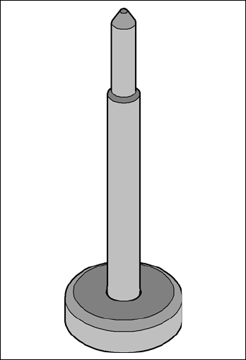
6.14 Support pin
Item no. 00119680-xx Support pin
Wide boards tend to deflect during placement such that, under certain circumstances, the compo-
nents can no longer be placed with the desired accuracy. Highly curved PCBs also affect the
placement accuracy. This problem can be easily rectified by fitting support pins on the lifting table.
6
Fig. 6.14 - 1 Support pin
6 Station extensions Instruction manual SIPLACE SX1/SX2 Edition V2 and V3
6.15 Smart Pin Support From software version SC.713.1 Edition 12/2020
334
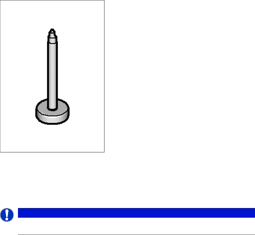
6.15 Smart Pin Support
Item no. 03089621-xx Smart Pin Support
Item no. 03087404-xx Magazine SPS L10 assembly
Item no. 03087508-xx Magazine SPS Q10 assembly
Wide boards tend to deflect during placement such that, under certain circumstances, the compo-
nents can no longer be placed with the desired accuracy. Highly curved PCBs also affect the
placement accuracy. This problem can be easily rectified by fitting support pins on the lifting table.
6
Fig. 6.15 - 1 Support pin
The support pins are automatically placed on the lifting table with the help of the Smart Pin Sup-
port
option. A gripper unit is used to pick the support pins up from special magazines and place
them in the prescribed positions.
6
PLEASE NOTE
For a detailed description, see the "Smart Pin Support User Guide", German+English
[item no. 00197001-xx]