00198661-02_UM_SX12-V3_EN.pdf - 第123页
Instruction manual SIPLACE SX1/SX2 Edition V2 and V3 3 Technical data and assemblies From software version SC.713.1 Edition 12/2020 3.7 Placement head 123 3.7.2.1 Overview 3 Fig. 3.7 - 2 SIPLACE C&P20 P - overview (1…

3 Technical data and assemblies Instruction manual SIPLACE SX1/SX2 Edition V2 and V3
3.7 Placement head From software version SC.713.1 Edition 12/2020
122
3.7.2 SIPLACE SpeedStar C&P20 P on the SIPLACE SX1/SX2 V2
3
The SIPLACE SX1/SX2 V2 uses the SIPLACE SpeedStar C&P20 for top placement performance.
3
CAUTION
Always take hold of the handle to push the placement head
The placement head may only be moved by pushing manually against the handle provid-
ed.
Instruction manual SIPLACE SX1/SX2 Edition V2 and V3 3 Technical data and assemblies
From software version SC.713.1 Edition 12/2020 3.7 Placement head
123
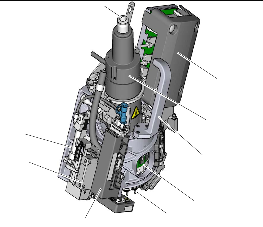
3.7.2.1 Overview
3
Fig. 3.7 - 2 SIPLACE C&P20 P - overview
(1) Compressed air connection for 20 Venturi nozzles in the pickup/placement and holding circuit
(2) "Vacuum sensor hold circuit" board
(3) Star motor
(4) Handle
(5) DP drive, 20 drives
(6) Star with 20 nozzles
(7) Pressure control valve
(8) Z motor (linear motor)
(9) Return cylinder
(5)
(1)
(7)
(2)
(3)
(4)
(6)
(8)
(9)
3 Technical data and assemblies Instruction manual SIPLACE SX1/SX2 Edition V2 and V3
3.7 Placement head From software version SC.713.1 Edition 12/2020
124
3.7.2.2 Technical data SIPLACE SpeedStar (C&P20 P)
3
SIPLACE SpeedStar (C&P20 P)
With component camera
type 23
With component camera
type 41
Component range
*a
*)a Please note that the placeable component range is also affected by the pad geometry, the customer-spe-
cific standards, the component packaging tolerances and the component tolerances.
01005 to 2220, Melf, SOT,
SOD
0201 (metric) to 2220, Melf,
SOT, SOD, Bare-Die, Flip-
Chip
Component spec.
Max. height
Min. lead pitch
Min. lead width
Min. ball pitch
Min. ball diameter
Min. dimensions
Max. dimensions
Max. weight
4 mm
250 µm
100 µm
400 µm
200 µm
0.18 mm x 0.18 mm
6mm x 6 mm
1 g
4 mm
80 µm
30 µm
100 µm
50 µm
0.12 mm x 0.12 mm
6 mm x 6 mm
1 g
Set-down force 1.3 N ± 0.5 N (default value)
0.5 N - 4.5 N
Touchless Placement
Nozzle types 40xx 40xx
X/Y accuracy
*b
*)b The accuracy values fulfill the conditions in the SIPLACE scope of supply and services.
± 41µm / 3σ ± 41µm / 3σ
Angular accuracy ± 0.5° / 3σ ± 0.5° / 3σ
Illumination level 5 5