00198661-02_UM_SX12-V3_EN.pdf - 第179页
Instruction manual SIPLACE SX1/SX2 Edition V2 and V3 3 Technical data and assemblies From software version SC.713.1 Edition 12/2 020 3.11 Component tro lley 179 3.1 1.8 T ape con t ainer 3.1 1.8.1 Desc ription The tape c…
3 Technical data and assemblies Instruction manual SIPLACE SX1/SX2 Edition V2 and V3
3.11 Component trolley From software version SC.713.1 Edition 12/2020
178
3.11.7 Mount for the additional reel for the changeover table
3
Fig. 3.11 - 7 Mount of additional tape reel
(1) Mount of additional tape reel, item no. 03075622-xx
(2) Mounting device for the support
X-Series feeder modules can process component tapes without problems if the lateral offset be-
tween the feeder module and the tape reel does not exceed 60 mm. If a predefined setup means
that the maximum permitted offset cannot be maintained, we recommend that you use the mount
for an additional tape reel (
item 1). Simply insert the mount into the holder (item 2) and push it
until the offset is less than the maximum permitted value of 60 mm. The component trolley has 5
holders in total. Each tape reel mount can hold 2 tape reels, which means that up to ten 19" (483
mm) tape reels can be positioned above the tape container.
Max. 60 mm
(1)
(2)
Instruction manual SIPLACE SX1/SX2 Edition V2 and V3 3 Technical data and assemblies
From software version SC.713.1 Edition 12/2020 3.11 Component trolley
179
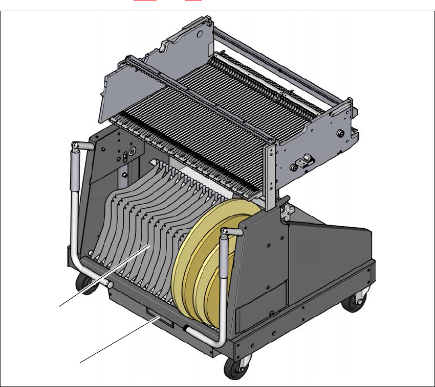
3.11.8 Tape container
3.11.8.1 Description
The tape container can hold tape reels up to 19" (483 mm) in diameter. The insertion of separating
plates is described in section 5.9.5
page 264.
3
Fig. 3.11 - 8 Component trolley, SIPLACE SX1/SX2, with tape container
(1) Tape container with separating plates
(2) Waste tape container
(1)
(2)
3 Technical data and assemblies Instruction manual SIPLACE SX1/SX2 Edition V2 and V3
3.11 Component trolley From software version SC.713.1 Edition 12/2020
180
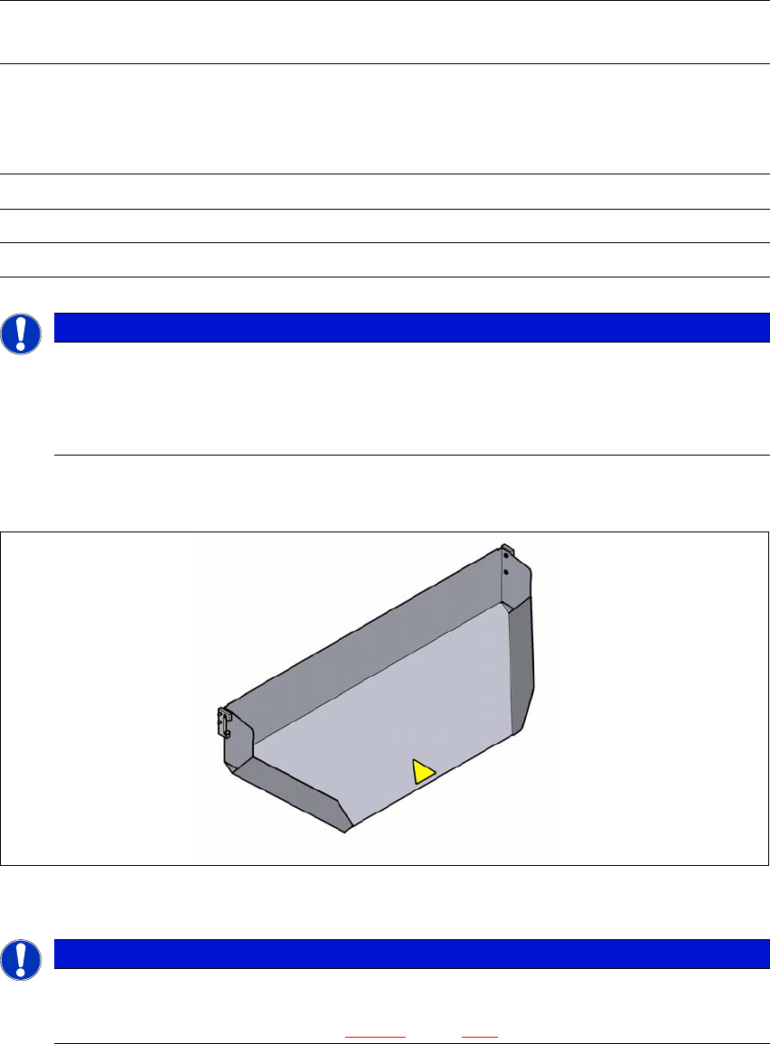
3.11.8.2 Maximum tape reel diameter in relation to the PCB conveyor height
3
3
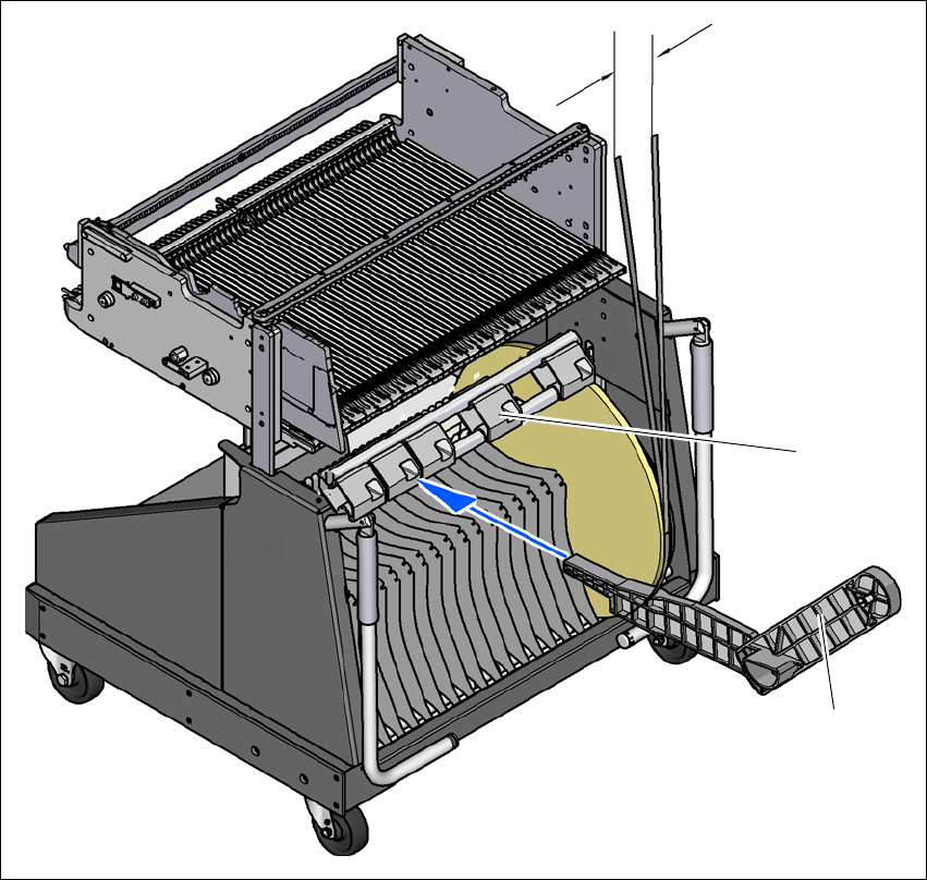
3.11.9 Used tape chute
3
Fig. 3.11 - 9 Used tape chute for the component trolley COT insert
3
3
Without mount for the
additional tape reel
With mount for the
additional tape reel
PCB conveyor
height
of the component
trolley
Tape reel diameter Tape reel diameter
without spindle with spindle
900 mm 19" 17" 15"
930 mm 19" 19" 17"
950 mm 19" 19" 19"
PLEASE NOTE
Using spindles
SIPLACE SX1/SX2 component trolleys do not generally need spindles.
Use spindles if the error message "Timeout" appears frequently on the X feeder mod-
ule.
PLEASE NOTE
The used tape chute for the SIPLACE SX1/SX2 can only be installed on the component
trolley COT insert
for the SIPLACE SX1/SX2 (see fig. 5.15 - 4
, page 286).