00198661-02_UM_SX12-V3_EN.pdf - 第79页
Instruction manual SIPLACE SX1/SX2 Edition V2 and V3 2 Operation al safety From software version SC.713.1 Edition 12/2020 2.6 Safety features 79 Adjust the height on the outer plate for each product so that n obody can…
2 Operational safety Instruction manual SIPLACE SX1/SX2 Edition V2 and V3
2.6 Safety features From software version SC.713.1 Edition 12/2020
78
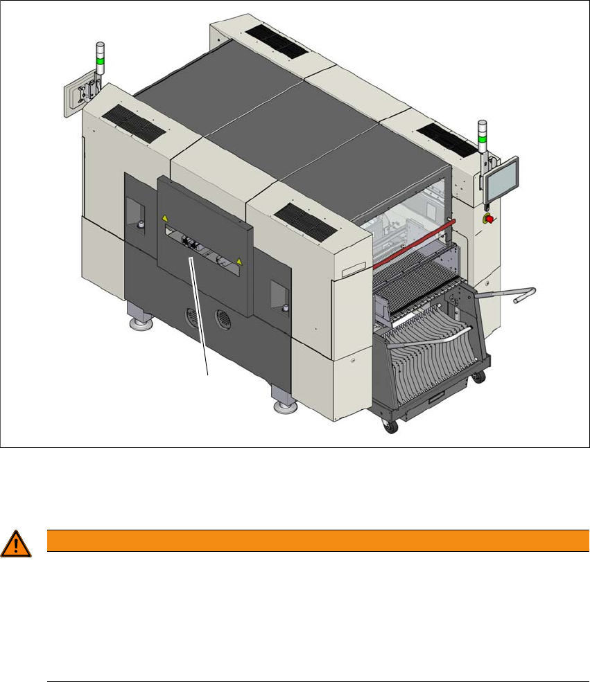
2.6.2 Hand guard on the board conveyor
The hand guard on the PCB conveyor prevents people reaching into the placement machine,
when it is in operation.
If a SIPLACE placement machine SX1/SX2 is operated outside a line, you will need to fit the hand
guard on the input and output conveyors of this placement machine.
2
Fig. 2.6 - 3 Hand guard on the placement machine SX1/SX2
(1) Hand guard
2
Fit the hand guard (1) to the input conveyor and to the output conveyor.
WARNING
DANGER OF CRUSHING!
If the hand guard is not fitted, reaching into the board conveyor could lead to injuries to
the arms and hands.
Only operate an SIPLACE SX1/SX2 placement machine outside the line if there is
a hand guard fitted to the input and output conveyors.
The operating company is responsible for ensuring that the hand guard is fitted.
(1)

Instruction manual SIPLACE SX1/SX2 Edition V2 and V3 2 Operational safety
From software version SC.713.1 Edition 12/2020 2.6 Safety features
79
Adjust the height on the outer plate for each product so that nobody can reach into the board
conveyor from below.
Adjust the height on the outer plate for each product so that nobody can reach into the board
conveyor from above.
Adjust the height so that the board with the components can be transported safely through
the conveyor system.
2
PLEASE NOTE
Maximum height of board
Observe the maximum height of the board with the highest component.
2 Operational safety Instruction manual SIPLACE SX1/SX2 Edition V2 and V3
2.6 Safety features From software version SC.713.1 Edition 12/2020
80
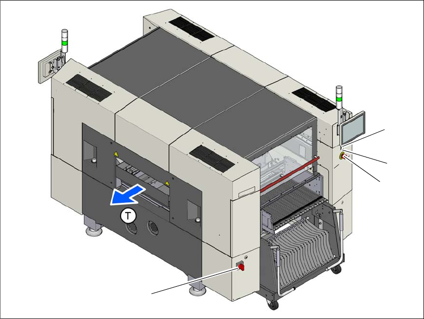
2.6.3 Switches and buttons on the placement machine
2.6.3.1 Position of switches and buttons on the placement machine
2
Fig. 2.6 - 4 Position of switches and buttons - View of the PCB output side
(1) Main switch
(2) Start button (white)
(3) Stop button (black)
(4) EMERGENCY STOP button
(T) PCB transport direction
(2)
(1)
(3)
(4)