00198661-02_UM_SX12-V3_EN.pdf - 第213页
Instruction manual SIPLACE SX1/SX2 Edition V2 and V3 4 Setting up and commissioning From software version SC.713.1 Edition 12/2020 4.3 Setting up the placement machine 213 4.3.7.2 Machine foot clearances fo r the PCB dua…
4 Setting up and commissioning Instruction manual SIPLACE SX1/SX2 Edition V2 and V3
4.3 Setting up the placement machine From software version SC.713.1 Edition 12/2020
212
4.3.7 Machine foot clearances and the stationary PCB conveyor edges
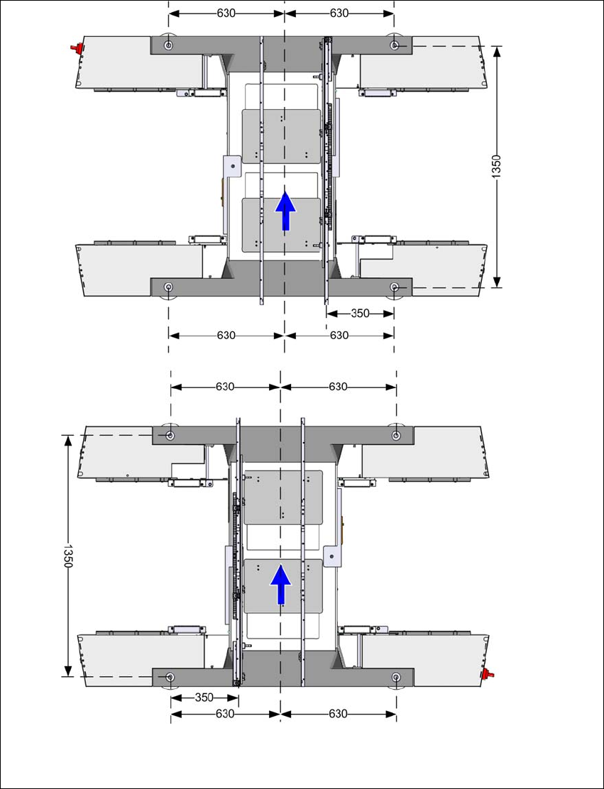
4.3.7.1 Machine foot clearances for the PCB single conveyor
4
Fig. 4.3 - 5 Machine foot clearances for the PCB single conveyor in millimeters
Fixed conveyor side at maxi-
mum right position
a
.
Fixed conveyor side at
maximum left position
a
.
a) The value depends on the position of the fixed side.
All dimensions in millimeters.
Instruction manual SIPLACE SX1/SX2 Edition V2 and V3 4 Setting up and commissioning
From software version SC.713.1 Edition 12/2020 4.3 Setting up the placement machine
213
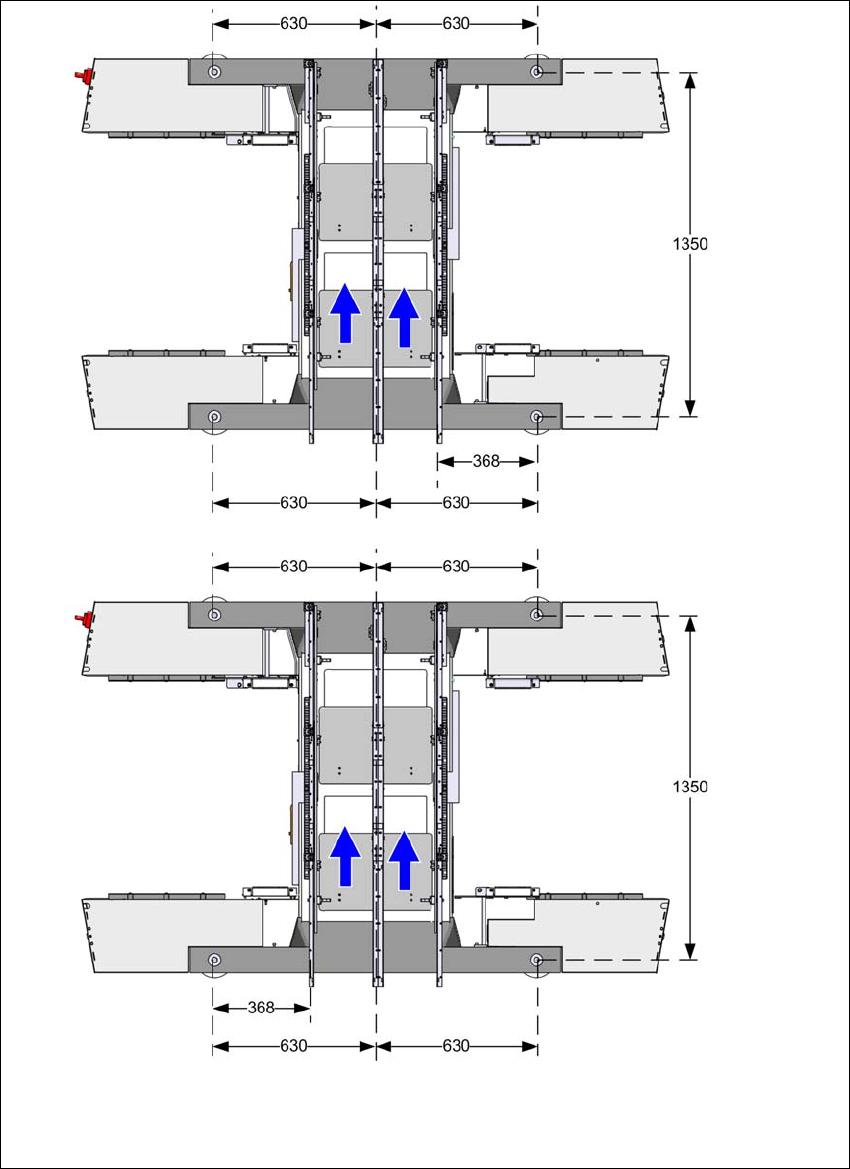
4.3.7.2 Machine foot clearances for the PCB dual conveyor
4
Fig. 4.3 - 6 Machine foot clearances for the PCB dual conveyor in millimeters
Fixed conveyor side at
maximum left position
a
.
Fixed conveyor side at maximum
right position
a
.
a) The value depends on the position of the fixed side.
All dimensions in millimeters.
4 Setting up and commissioning Instruction manual SIPLACE SX1/SX2 Edition V2 and V3
4.3 Setting up the placement machine From software version SC.713.1 Edition 12/2020
214
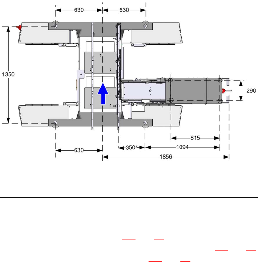
4.3.7.3 Machine foot clearances for the placement machine and WPC5/WPC6
4
Fig. 4.3 - 7 Machine foot clearances for the placement machine and WPC5/WPC6 in millimeters
4.3.8 Integrating the placement machine into the line
Observe the general warnings in section 4.3.1, page 203.
Observe the warnings for transportation of the placement machine in section 4.3.2, page 204.
For details of tools and equipment, refer to section 4.3.5, page 207.
4.3.8.1 Aligning and adjusting the placement machines in the line
With the fork-lift, raise the placement machine until the weight is taken off the machine feet.
Determine the PCB conveyor height for the placement machine in the line and use the hexa-
gon socket head screw to adjust the height approximately.
You may need to fit the machine feet to the relevant PCB conveyor height (see 4.3.6 on page
208).
Position the placement machine on the free location on the line using the fork-lift.
Pay attention to the alignment of the PCB conveyors and check the distance to the previous
placement machine.
a) The value depends on the position of the fixed side.
All dimensions in millimeters.