00198661-02_UM_SX12-V3_EN.pdf - 第125页
Instruction manual SIPLACE SX1/SX2 Edition V2 and V3 3 Technical data and assemblies From software version SC.713.1 Edition 12/2020 3.7 Placement head 125 3.7.3 Sensor for the component reject bin The sensor fo r the com…
3 Technical data and assemblies Instruction manual SIPLACE SX1/SX2 Edition V2 and V3
3.7 Placement head From software version SC.713.1 Edition 12/2020
124
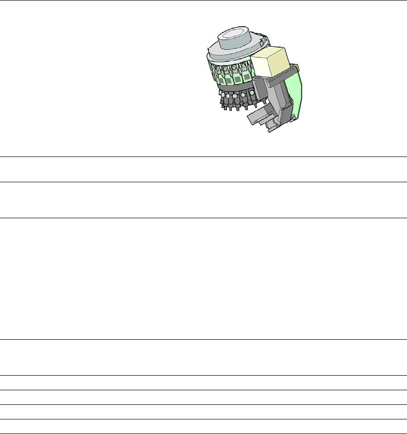
3.7.2.2 Technical data SIPLACE SpeedStar (C&P20 P)
3
SIPLACE SpeedStar (C&P20 P)
With component camera
type 23
With component camera
type 41
Component range
*a
*)a Please note that the placeable component range is also affected by the pad geometry, the customer-spe-
cific standards, the component packaging tolerances and the component tolerances.
01005 to 2220, Melf, SOT,
SOD
0201 (metric) to 2220, Melf,
SOT, SOD, Bare-Die, Flip-
Chip
Component spec.
Max. height
Min. lead pitch
Min. lead width
Min. ball pitch
Min. ball diameter
Min. dimensions
Max. dimensions
Max. weight
4 mm
250 µm
100 µm
400 µm
200 µm
0.18 mm x 0.18 mm
6mm x 6 mm
1 g
4 mm
80 µm
30 µm
100 µm
50 µm
0.12 mm x 0.12 mm
6 mm x 6 mm
1 g
Set-down force 1.3 N ± 0.5 N (default value)
0.5 N - 4.5 N
Touchless Placement
Nozzle types 40xx 40xx
X/Y accuracy
*b
*)b The accuracy values fulfill the conditions in the SIPLACE scope of supply and services.
± 41µm / 3σ ± 41µm / 3σ
Angular accuracy ± 0.5° / 3σ ± 0.5° / 3σ
Illumination level 5 5
Instruction manual SIPLACE SX1/SX2 Edition V2 and V3 3 Technical data and assemblies
From software version SC.713.1 Edition 12/2020 3.7 Placement head
125
3.7.3 Sensor for the component reject bin
The sensor for the component reject bin monitors whether the reject bin is seated correctly in its
mount.
– If the reject bin was not inserted correctly, the placement machine cannot be started.
– If the reject bin jumps out of its mount during the placement process, the placement machine
will be stopped immediately to avoid a head crash.
3.7.4 Vacuum pump (optional)
The vacuum pump for the SIPLACE SpeedStar is fitted behind the COT inserts at location 1, in-
side the machine base. There are two types available:
– Vacuum pump VX4.25
– Vacuum pump
VX4.25/0-47 IE3
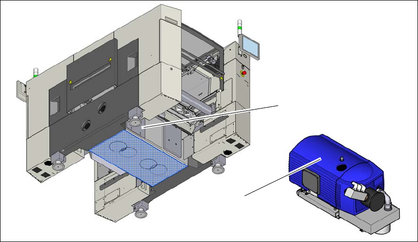
3.7.4.1 Overview - type VX4.25
Item no. 03128463-xx Vacuum pump VX4.25
3
Fig. 3.7 - 3 Overview - vacuum pump
(1) Installation location for vacuum pump
(2) Vacuum pump VX 4.25
(1)
(2)
3 Technical data and assemblies Instruction manual SIPLACE SX1/SX2 Edition V2 and V3
3.7 Placement head From software version SC.713.1 Edition 12/2020
126
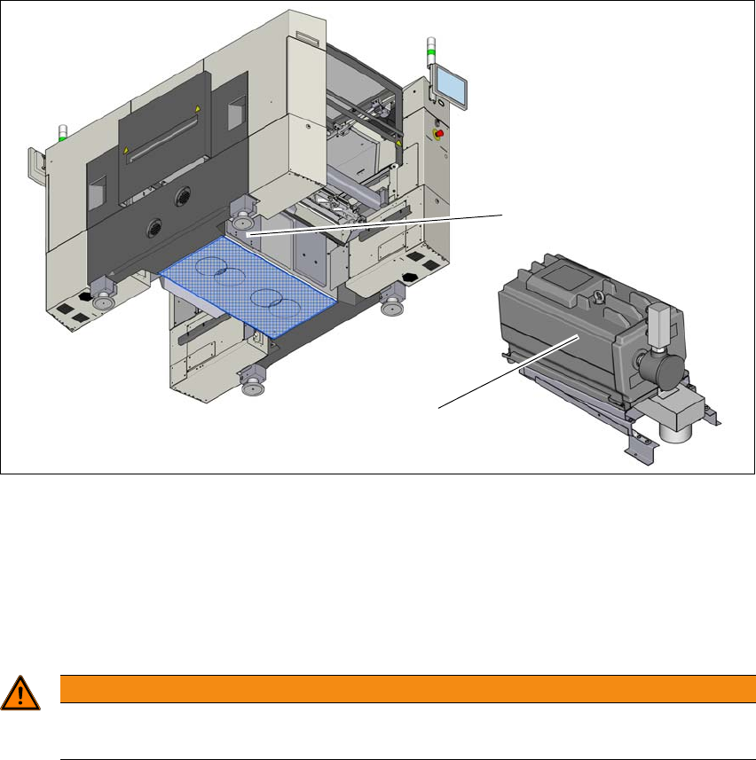
3.7.4.2 Overview - type VX4.25/0-47 IE3
Item no. 03224400-xx Vacuum pump VX4.25/0-47 IE3
3
Fig. 3.7 - 4 Overview - vacuum pump
(1) Installation location for vacuum pump
(2) Vacuum pump VX 4.25 IE3
3.7.4.3 Safety instructions for vacuum pumps
3
(1)
(2)
WARNING
Observe the safety instructions
Please observe the safety instructions in the instruction manual supplied.