00198661-02_UM_SX12-V3_EN.pdf - 第286页
5 Tasks at the placement machine Instruction manual SIPLACE SX1/ SX2 Edition V2 and V3 5.15 Docking the component trolley in or out From software versi on SC.713.1 Edition 12/2020 286 5.15.4 Docking the component trolley…
Instruction manual SIPLACE SX1/SX2 Edition V2 and V3 5 Tasks at the placement machine
From software version SC.713.1 Edition 12/2020 5.15 Docking the component trolley in or out
285
5
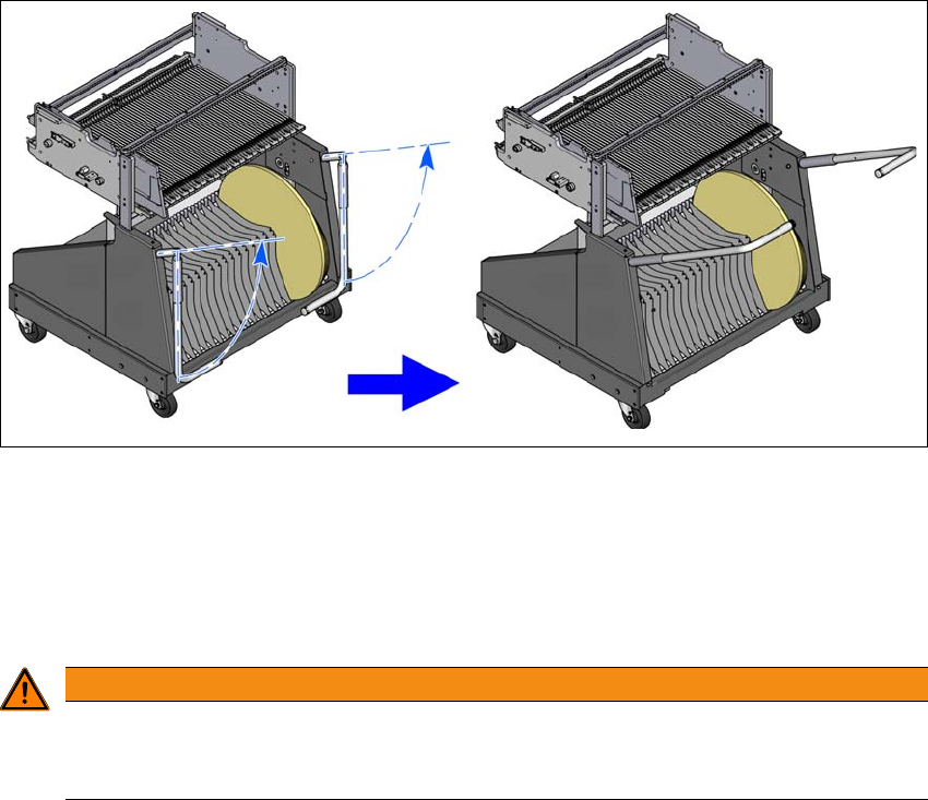
Fig. 5.15 - 3 Component trolley - swivel handles up to push
With both hands on the handles, pull the component trolley out of the placement machine.
5.15.3 Safety instructions for moving the component trolley
5
Always hold the handles with both hands when you want to move the component trolley.
Remember that a component trolley with the full complement of feeder modules can tip over
sideways or forward on gradients of 20° or more.
Make sure that the surface on which the trolley is moved has a significantly smaller gradient.
The floor underneath the placement machine may not exceed an incline of 0.63%. This cor-
responds to an incline of 5 mm over a distance of 800 mm (e.g. the width of a changeover
table).
Be careful not to collide with obstacles. The trolley could tip forward if it is traveling fast
enough.
WARNING
Avoid accidents!
To prevent accidents, ALWAYS follow the rules listed below when you move the compo-
nent trolley.
5 Tasks at the placement machine Instruction manual SIPLACE SX1/SX2 Edition V2 and V3
5.15 Docking the component trolley in or out From software version SC.713.1 Edition 12/2020
286
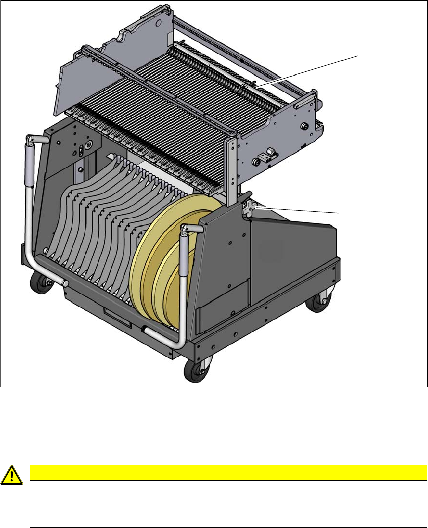
5.15.4 Docking the component trolley
5
Fig. 5.15 - 4 Docking the component trolley
(1) Locking latches
(2) Height setting for fine adjustment to the machine height
5
CAUTION
Pushing in component trolley!
When pushing the component trolley into the placement machine, make sure that
you do not hit obstacles with the locking latches.
(2)
(1)
Instruction manual SIPLACE SX1/SX2 Edition V2 and V3 5 Tasks at the placement machine
From software version SC.713.1 Edition 12/2020 5.15 Docking the component trolley in or out
287
I 5
5
5
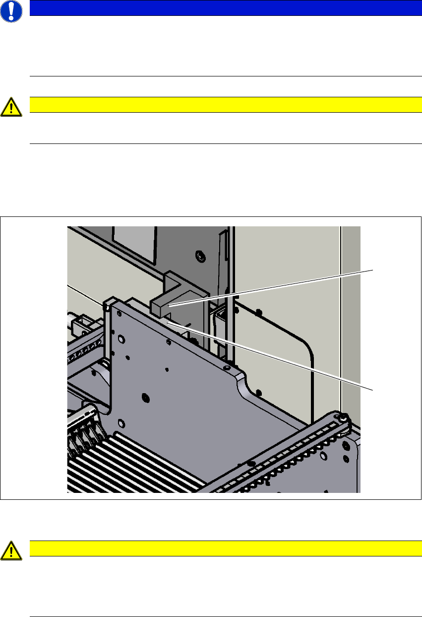
Carefully push the component trolley into the placement machine as far as the stop. The stop
block
(2) of the changeover table must fit under the bracket for the table height check (1) on
the machine feed-in (right and left side).
5
Fig. 5.15 - 5 Table height check
5
PLEASE NOTE
Cut tapes flush
If you do not cut tapes off flush at the front end of the X feeder modules, the emptied tapes
will not enter the empty tape duct.
Cut the tapes off flush, before you dock the component trolley into place.
CAUTION
Position of placement head!
Check that the placement head is outside the range of the component trolley.
CAUTION
Risk of head crash!
When dismantling one of the two brackets (left and right side) for the table height check,
there is a risk of a head crash due to changeover tables being too high.
Do not dismantle the brackets.
(1)
(2)