00198661-02_UM_SX12-V3_EN.pdf - 第297页
Instruction manual SIPLACE SX1/SX2 Edition V2 and V3 6 Station e xtensi ons From software version SC.713.1 Edition 12/2020 6.1 Nozzle changer 297 6.1.2.5 Position of the nozzle changer for the SIPLACE MultiS tar 6 Fig. 6…
6 Station extensions Instruction manual SIPLACE SX1/SX2 Edition V2 and V3
6.1 Nozzle changer From software version SC.713.1 Edition 12/2020
296
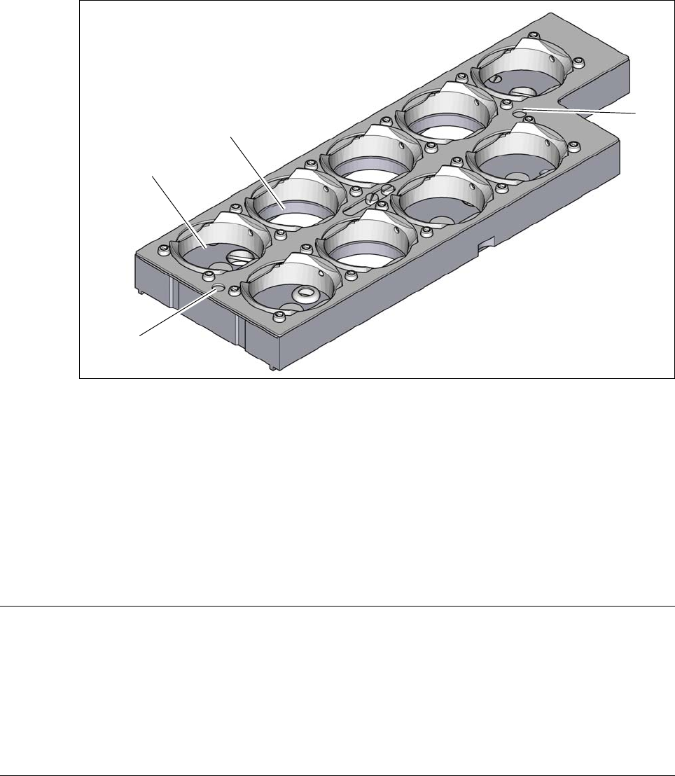
6.1.2.3 Nozzle magazine with 9 garages for 28xx nozzles
6
Fig. 6.1 - 5 Nozzle magazine for 28xx nozzles
(1) 5 garages for 28xx nozzles with a maximum nozzle length of 12.5 mm
(garage numbers 1, 5, 6, 8 and 9)
(2) 4 garages for 28xx nozzles with a maximum nozzle length of 16.5 mm
(garage numbers 2, 3, , 4 and 7)
(3) Fiducials (only visible when locking plate open)
6.1.2.4 Technical data
6
(1)
(2)
(3)
(3)
Nozzle changer for the SIPLACE MultiStar
Number of magazines per location
*a
4
Max. number of nozzle garages per location 69
Standard configuration per location 3 magazines with 60 x 20xx nozzle garages
1 magazine with 9 x 28xx nozzle garages
Nozzle types 20xx, 28xx
*)a All magazines in the nozzle changer must be configured.
Instruction manual SIPLACE SX1/SX2 Edition V2 and V3 6 Station extensions
From software version SC.713.1 Edition 12/2020 6.1 Nozzle changer
297
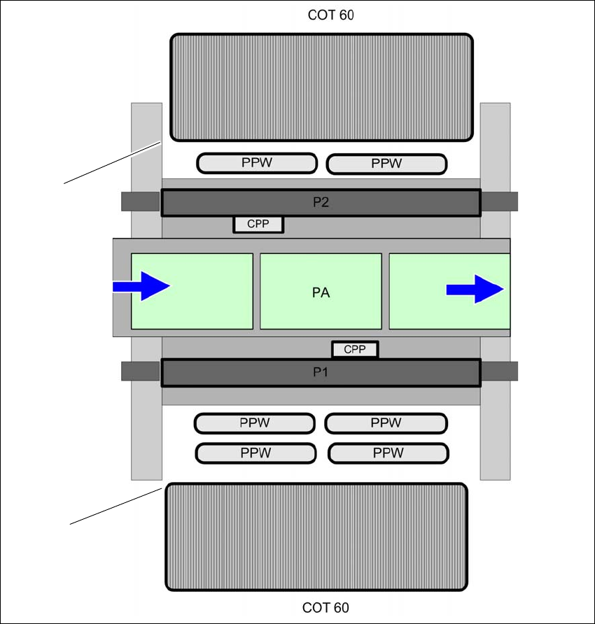
6.1.2.5 Position of the nozzle changer for the SIPLACE MultiStar
6
Fig. 6.1 - 6 Position of nozzle changer for the SIPLACE MultiStar - example
6
(1) Component trolley in the inner position
(2) Component trolley in the outer position
(NC) Nozzle changer
(PA) Placement area
(1)
(2)
6 Station extensions Instruction manual SIPLACE SX1/SX2 Edition V2 and V3
6.1 Nozzle changer From software version SC.713.1 Edition 12/2020
298
6.1.3 Assembling the nozzle changer C&P20 P / C&P20 P2 / CPP
The nozzle changers are fixed to the COT insert.
Align the nozzle changer so that the sloping side points towards the COT insert.
6
6.1.3.1 Notes on operation
When you fill a magazine with a certain nozzle type for the first time, attach an adhesive label
to identify the type.
6
Open the locking plate and place the nozzles in the nozzle holders.
Close the locking plate so that the nozzles cannot drop out of the magazines.
6
6
Programming the nozzle changer is described in the SIPLACE Pro instruction manual.
6.1.3.2 Changing the magazine
Press the lever (item 1 in fig. 6.1 - 7, page 299), to release the magazine from the balls of the
snap fasteners (item 5 in fig. 6.1 - 7
, page 299). Lift the magazine off the base.
WARNING
Risk of head crashes with mixed configurations!
There is a risk of head crashes with mixed configurations.
Only install the associated nozzle changer for each placement head, with the nozzle
magazines for the respective placement head.
PLEASE NOTE
6
Fill the magazines outside the placement machine and only replace complete mag-
azines.
CAUTION
Filling up magazines!
Before you fill magazines, make sure that all the nozzles on the Collect&Place head
have
been returned to their magazines.
PLEASE NOTE
Risk of jamming!
If components fall onto magazines, there is a risk that the locking plate could jam.
Do not allow components to drop onto the magazines.
You should therefore regularly clean the magazines and free locations.