00198661-02_UM_SX12-V3_EN.pdf - 第170页
3 Technical data and assemblies I nstruction manual SIPLACE SX1/S X2 Edition V2 and V3 3.11 Component trolley From software version SC.713.1 Edition 12/ 2020 170 3.1 1 Component trolley Item no. 005199 22-xx Component tr…
Instruction manual SIPLACE SX1/SX2 Edition V2 and V3 3 Technical data and assemblies
From software version SC.713.1 Edition 12/2020 3.10 X feeder modules
169
3.10.6.2 Safety instructions
3.10.6.3 Technical data
3
3
3
3
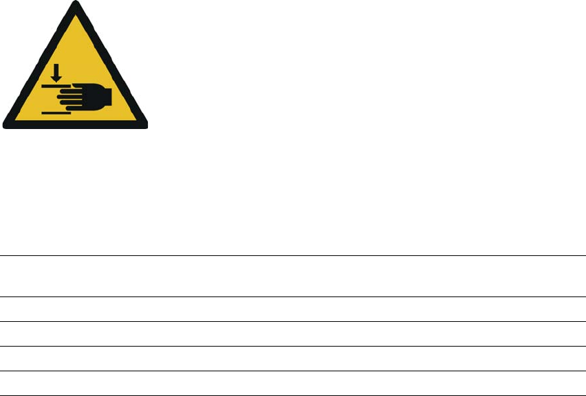
Warning about hand injuries
There is a risk of injury to hands when folding the extender arm up
into the park position.
When folding up the extender arm, make sure that you do not
trap your hand between the extender arm and the
SIPLACE PowerConnector X.
Length 648.4 mm (folded in)
866.9 mm (folded out)
Width 34.4 mm
Height 188.4 mm
Occupied locations 3
Weight 3.2 kg
3 Technical data and assemblies Instruction manual SIPLACE SX1/SX2 Edition V2 and V3
3.11 Component trolley From software version SC.713.1 Edition 12/2020
170
3.11 Component trolley
Item no. 00519922-xx Component trolley for SIPLACE SX1/SX2 with 60 tracks
Item no. 00519722-xx Component trolley for SIPLACE SX1/SX2 with 30 tracks
The SIPLACE SX1/SX2 placement machines can accommodate two SIPLACE SX1/SX2 compo-
nent trolleys, each with 60 tracks. If a WPC5/WPC6 is set up at one of the locations, the other
location can accommodate a component trolley with 30 tracks.
3
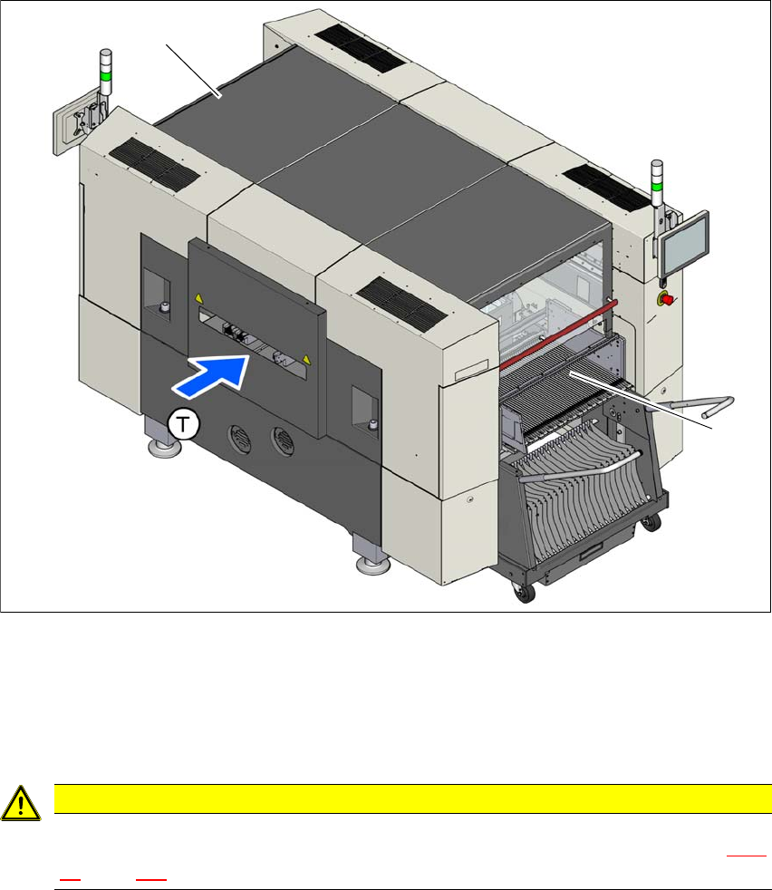
Fig. 3.11 - 1 Component trolley locations, SIPLACE SX1/SX2
(1) Location 1
(2) Location 2
(T) Direction of PCB transport
3
CAUTION
The SIPLACE SX1/SX2 component trolleys may only be docked onto locations at which
the component trolley COT insert for the SIPLACE SX1/SX2 has been installed (fig. 5.15
- 4, page 286 ).
(2)
(1)
Instruction manual SIPLACE SX1/SX2 Edition V2 and V3 3 Technical data and assemblies
From software version SC.713.1 Edition 12/2020 3.11 Component trolley
171
3.11.1 Structure
The component trolleys are stand-alone modules that can be set up with feeders at an external
setup area. This means that the production process only has to be interrupted briefly in order to
change the component trolley.
The component trolley essentially consists of the chassis, the changeover table for holding the
feeder modules, the tape reel container and the waste tape container. There are two different com-
ponent trolleys available. One component trolley has a changeover table with 60 tracks and the
other one has a changeover table with 30 tracks. The component trolley with 30 tracks must be
set up next to the WPC5/WPC6.
3
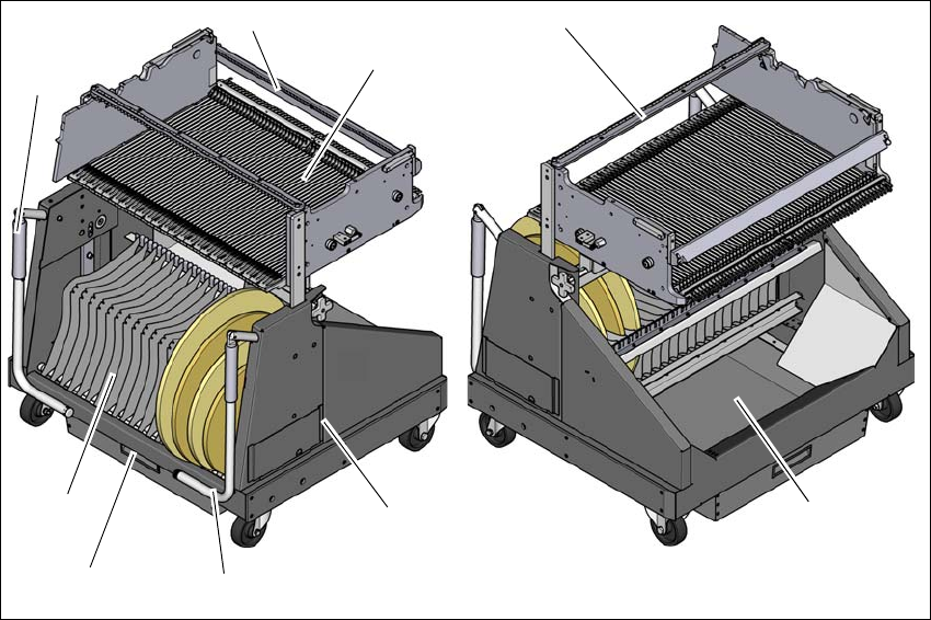
Fig. 3.11 - 2 Component trolley, SIPLACE SX1/SX2 with 60 tracks, front and rear view
(1) Chassis
(2) Changeover table
(3) Tape container
(4) Waste tape container
(5) Handle
(6) Hand guard
(1)
(2)
(5)
(4)
(3)
(5)
(4)
(6)
(6)