00198661-02_UM_SX12-V3_EN.pdf - 第336页
6 Station extensions Instructio n manual SIPLACE SX1/SX2 Edition V2 and V3 6.15 Smart Pin Support From software version SC.713.1 Edition 12/ 2020 336 6 Fig. 6.15 - 3 Smart Pin Support - magazine type Q10 6 Fig. 6.15 - 4 …
Instruction manual SIPLACE SX1/SX2 Edition V2 and V3 6 Station extensions
From software version SC.713.1 Edition 12/2020 6.15 Smart Pin Support
335
6
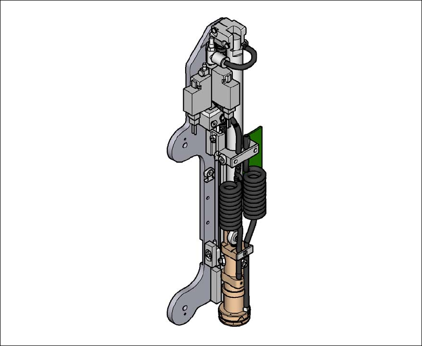
Fig. 6.15 - 2 Gripper unit for Smart Pin Support
The gripper unit is fitted to the gantry. This gripper unit picks the support pins up from the pre-
scribed magazine and positions them on the lifting table. The positions of the support pins in the
placement machine can be defined for each board side, in the SIPLACE Pro Board Editor.
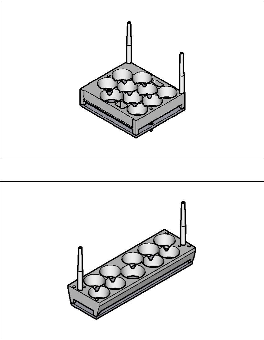
There are two different magazines available for automatic changeover of max. 10 support pins in
the various machine configurations. These magazines are fixed to a magazine holder and are fit-
ted to the component trolley COT insert.
– Smart Pin Support - magazine type Q10 [item no. 03087404-xx]
– Smart Pin Support - magazine type L10 [item no. 03087508-xx]
6 Station extensions Instruction manual SIPLACE SX1/SX2 Edition V2 and V3
6.15 Smart Pin Support From software version SC.713.1 Edition 12/2020
336
6
Fig. 6.15 - 3 Smart Pin Support - magazine type Q10
6
Fig. 6.15 - 4 Smart Pin Support - magazine type L10
Instruction manual SIPLACE SX1/SX2 Edition V2 and V3 6 Station extensions
From software version SC.713.1 Edition 12/2020 6.16 With LCD monitor and keyboard
337
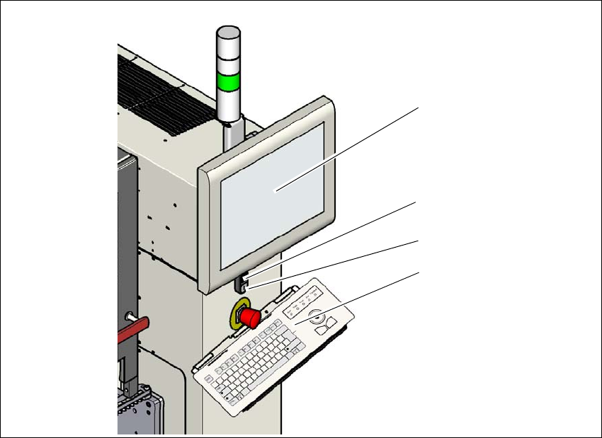
6.16 With LCD monitor and keyboard
The SIPLACE SX1/SX2 V2 features a multi-touch monitor with keyboard as a default.
Instead of the standard multi-touch monitor, you can configure a 15" LCD monitor with keyboard
at each of the SIPLACE SX1/SX2 V3 operating panels.
6
Fig. 6.16 - 1 With LCD monitor and keyboard
(1) LCD touchscreen
(2) Start button (white) on the placement machine
(3) Stop button (black) on the placement machine
(4) Keyboard
(1)
(4)
(2)
(3)