00198661-02_UM_SX12-V3_EN.pdf - 第172页
3 Technical data and assemblies I nstruction manual SIPLACE SX1/S X2 Edition V2 and V3 3.11 Component trolley From software version SC.713.1 Edition 12/ 2020 172 3 3 3.1 1.2 Description In the st andard version, the t ap…
Instruction manual SIPLACE SX1/SX2 Edition V2 and V3 3 Technical data and assemblies
From software version SC.713.1 Edition 12/2020 3.11 Component trolley
171
3.11.1 Structure
The component trolleys are stand-alone modules that can be set up with feeders at an external
setup area. This means that the production process only has to be interrupted briefly in order to
change the component trolley.
The component trolley essentially consists of the chassis, the changeover table for holding the
feeder modules, the tape reel container and the waste tape container. There are two different com-
ponent trolleys available. One component trolley has a changeover table with 60 tracks and the
other one has a changeover table with 30 tracks. The component trolley with 30 tracks must be
set up next to the WPC5/WPC6.
3
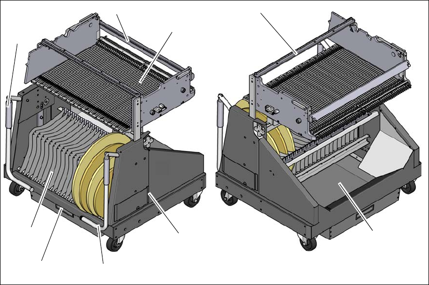
Fig. 3.11 - 2 Component trolley, SIPLACE SX1/SX2 with 60 tracks, front and rear view
(1) Chassis
(2) Changeover table
(3) Tape container
(4) Waste tape container
(5) Handle
(6) Hand guard
(1)
(2)
(5)
(4)
(3)
(5)
(4)
(6)
(6)
3 Technical data and assemblies Instruction manual SIPLACE SX1/SX2 Edition V2 and V3
3.11 Component trolley From software version SC.713.1 Edition 12/2020
172
3
3
3.11.2 Description
In the standard version, the tape reel container holds tape reels up to a size of 17" (432 mm).
There are two 5 mm wide gaps on the left and right, between the tape container and the compo-
nent trolley, for holding setup lists.
The pullout waste tape container can be found beneath the chassis. The cut waste tape travel
down a chute into the waste tape container, which must be emptied as it fills up.
The handles can be folded up or down.
3
CAUTION
Observe the safety instructions!
Observe the safety instructions in section 5.8.2, page 260 when you pull the tape re-
ject bin out of the component trolley.
CAUTION
Risk of breaking handles!
Risk of breaking handles when transporting the component trolley.
When transporting the component trolley, do not lift it by its handles.
Only use the handles to push the component trolley.
Use a fork-lift if you want to transport the component trolley or lift it off the pallet.
PLEASE NOTE
All component trolleys must be docked onto the
placement machine in order to operate it.
Fill any free locations with dummy feeder modules as described in
section 2.6.5
, page 91.
Instruction manual SIPLACE SX1/SX2 Edition V2 and V3 3 Technical data and assemblies
From software version SC.713.1 Edition 12/2020 3.11 Component trolley
173
3.11.3 Technical data
3
Component trolley dimensions
Component trolley with 60 tracks (length x
width)
Component trolley with 30 tracks (length x
width)
760 mm x 864 mm
760 mm x 471 mm
Height with folded-up handles
900 mm (PCB transport height:
930 mm (PCB transport height:
950 mm (PCB transport height:
934 mm
964 mm
984 mm
Weight of component trolley with 60 tracks
Without feeder modules
With feeder modules (fully configured)
Weight of component trolley with 30 tracks
Without feeder modules
With feeder modules (fully configured)
104 kg
266 kg
76 kg
157 kg
Tape reel diameter
Standard
maximum
to 432 mm (17“)
483 mm (19“)
Feeder locations
Component trolley with 60 tracks
Component trolley with 30 tracks
60 feeders with 8 mm
30 feeders with 8 mm
Component trolley changeover time < 1 minute