2OM-1104-001.pdf - 第126页
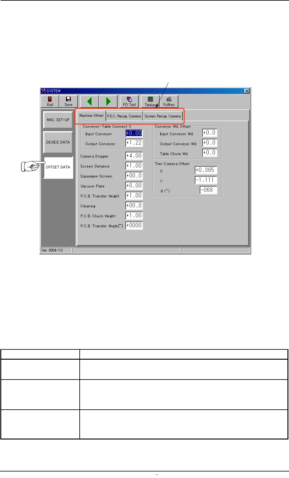
4.1 "Machine Offset" T ab This tab sheet enables the operator to set offset values for each section of the machine. • Sheet Layout When "Machine Offset" tab is pressed at the "OFFSET DA T A"…
4. "Offset Data" Submenu
• Window Layout
When the [OFFSET DATA] button is pressed in the "SYSTEM" submenu
bar, the following window appears.
Fig. 3D12 "Offset Data" Window (Submenu)
• Window Composition
*1 Tabs
The "Offset Data" window (submenu) is provided with three tab
sheets.
Every time a tab is pressed, the corresponding tab sheet appears.
Table 3D3
Tabs Description
Machine Offset This tab sheet enables the operator to set offset values for each
section of the machine.
P.E.C. Recog. Camera This tab sheet enables the operator to set offset values and magni-
fications of the P.E.C. recognition camera and gain & level (contrast
and brightness difference) of the fiducial mark.
Screen Recog. Camera This tab sheet enables the operator to set offset values and magni-
fications of the screen recognition camera and gain & level (contrast
and brightness difference) of the fiducial mark.
*1
0004-001 Chapter 1 4 19 AFU01EDTP
4.
"
Offset Data
"
Submenu
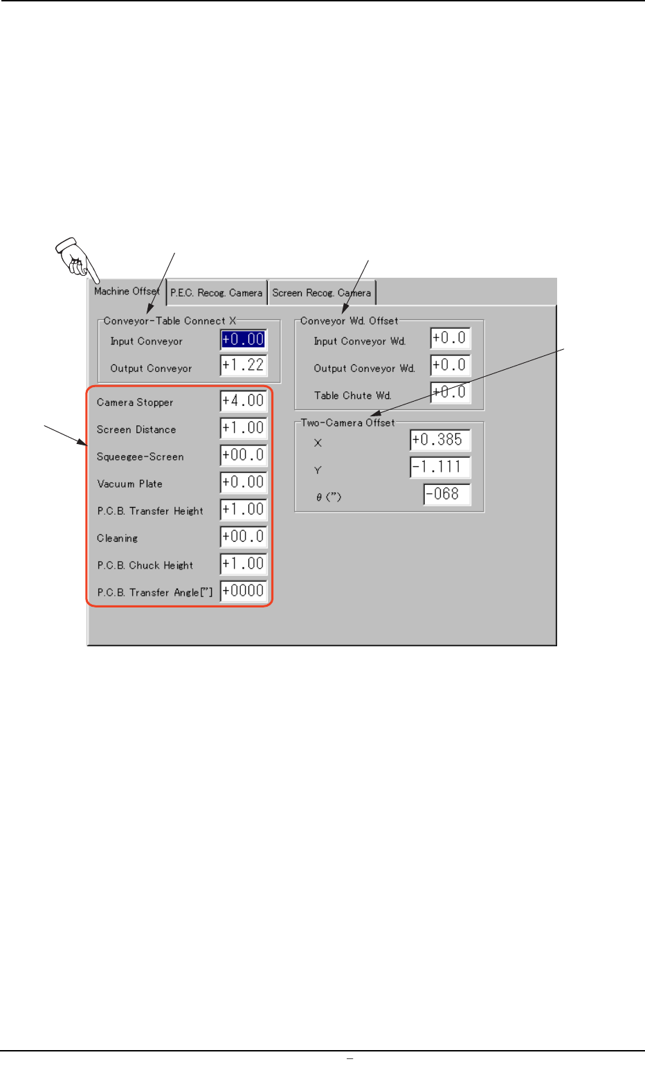
4.1 "Machine Offset" Tab
This tab sheet enables the operator to set offset values for each section
of the machine.
• Sheet Layout
When "Machine Offset" tab is pressed at the "OFFSET DATA" window
(submenu), the following tab sheet appears.
Fig. 3D13 "Machine Offset" Tab Sheet
• Sheet Layout
*1 Conveyor-Table Connect X (Horizontal)
Enter clearances (dimensions) in the X direction of the terminal
areas between the L/R conveyors and the table chute. The en-
tered values are used to change the specified ones.
*3
*1
*2
*4
0106-003 Chapter 1 4 20 AFU01EDTP
4.1
"
Machine Offset
"
Tab
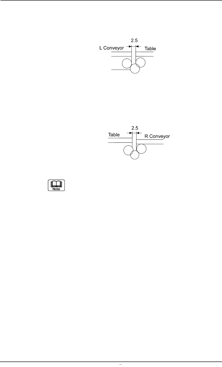
Input Conveyor : Enter an offset value based on the specified
one (2.0 mm) as a clearance (dimension) in
the X direction of the terminal area between
the L conveyor and the table chute.
Fig. 3D13-1
Output Conveyor : Enter an offset value based on the specified
one (2.0 mm) as a clearance (dimension) in
the X direction of the terminal area between
the R conveyor and the table chute.
Fig. 3D13-2
Make the ten-key window appear and enter the offset val-
ues in the text boxes.
*2 Conveyor Wd. Offset
Enter dimensions (widths) in the Y direction of the L/R conveyors
and the table chute through which a P.C.B. passes. The entered
values are used to change the specified ones in the pattern pro-
gram.
Input Conveyor Wd. : Enter an offset value (the dimension
representing the width through which
a P.C.B. on the L conveyor passes)
based on the specified one in the pat-
tern program.
Output Conveyor Wd. : Enter an offset value (the dimension
representing the width through which
a P.C.B. on the R conveyor passes)
based on the specified one in the pat-
tern program.
Table Chute Wd. : Enter an offset value (the dimension
representing the width through which
a P.C.B. on the table chute passes)
based on the specified one in the pat-
tern program.
0009-002 Chapter 1 4 21 AFU01EDTP
4.1
"
Machine Offset
"
Tab