2OM-1104-001.pdf - 第342页
Fig. 5C4 0106-002 Chapter 3 3 47 AFU01EMTP 3.2 Location of Sensors in T able Section
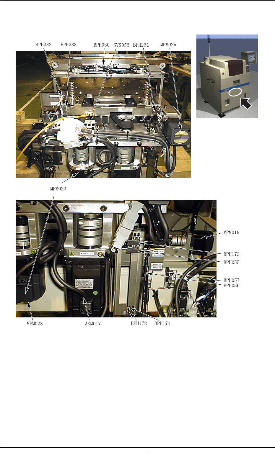
3.2 Location of Sensors in Table Section
3.2 Location of Sensors in Table Section
Fig. 5C3
0106-002 Chapter 3 3 46 AFU01EMTP
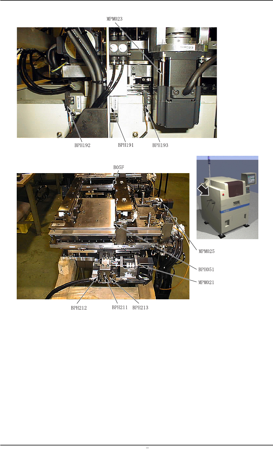
Fig. 5C4
0106-002 Chapter 3 3 47 AFU01EMTP
3.2 Location of Sensors in Table Section
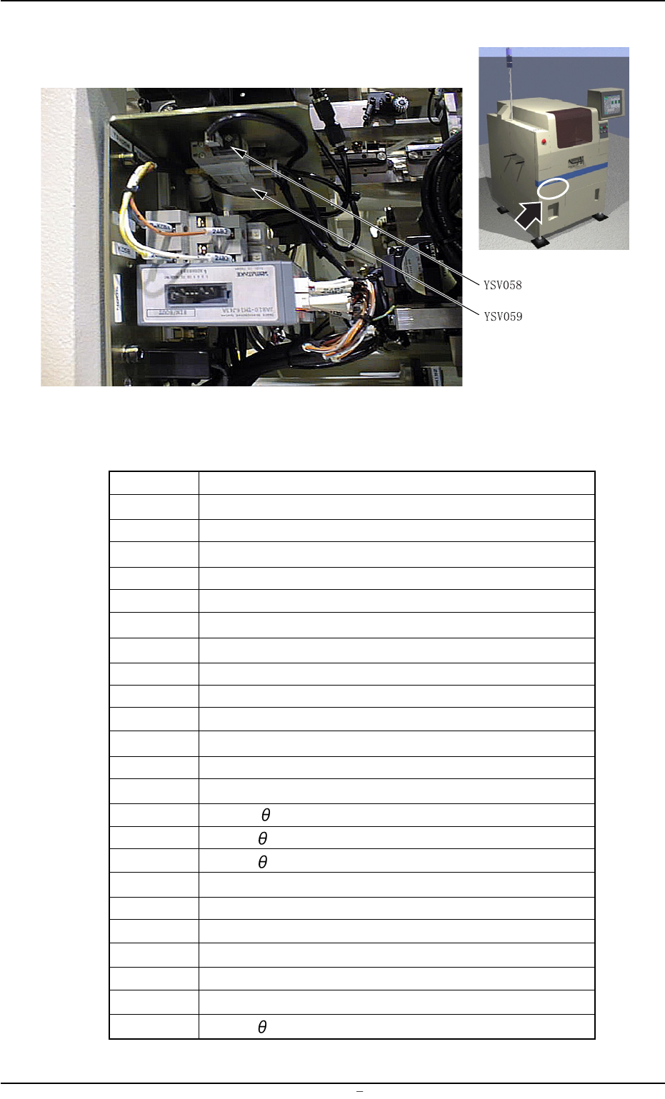
Fig. 5C5
Table 5C3
Symbols Name
BPH050 P.C.B. Horizontal Clamping Forward Limit
BPH051 Width Error Detection (Light Emitting Side)
B05F Width Error Detection (Light Receiving Side)
SVS052 Vacuum Switch
BPH055 Table Z-Axis Interlock
BPH056 Table X-Axis Interlock (+)
BPH057 Table X-Axis Interlock (-)
BPH171 Table Z-Axis Origin
BPH172 Table Z-Axis Limit (+)
BPH173 Table Z-Axis Limit (-)
BPH191 Table X-Axis Origin
BPH192 Table X-Axis Limit (+)
BPH193 Table X-Axis Limit (-)
BPH211 Table
-Axis Origin
BPH212 Table
-Axis Limit (+)
BPH213 Table
-Axis Limit (-)
BPH231 P.C.B. U/D Axis Origin
BPH232 P.C.B. U/D Axis Limit (+)
BPH233 P.C.B. U/D Axis Limit (-)
BPH251 Rail Axis Limit (+)
ASMD017 Table Z-Axis Servomotor
MPM019 Table X-Axis Pulse Motor
MPM021 Table
-Axis Pulse Motor
0106-002 Chapter 3 3 48 AFU01EMTP
3.2 Location of Sensors in Table Section