2OM-1104-001.pdf - 第29页
(13) Prntng. Correction (For .) X [mm], Y [mm], [ ] Set parameters to correct the relative position (trace quality) be- tween the P .C.B. and the screen kept when the squeegees move forward (from the rear to the front si…
(7) Screen Distance
Set the clearance between the screen and the upper surface of
the P.C.B. during printing operation.
Unit: mm
Data Input Range: -1.5 3.0
(8) Separation Mode
Set a parameter to determine whether or not the squeegees must
move up after the P.C.B. has descended or the P.C.B. must move
down after the squeegees have ascended when the screen frame
is separated from the P.C.B. after the completion of printing.
PCB Down : The squeegees move up after the P.C.B. has
descended.
Squeegee Up : The P.C.B. moves down after the squeegees
have ascended.
(9) Separation Speed [mm/s]
Set the speed at which the screen frame should be separated from
the P.C.B. after the end of printing.
Unit: mm/s
Data Input Range: 0.05
3.00
(10) Separation Acc. [mm/s
2
]
Set the acceleration rate at which the screen frame should be sepa-
rated from the P.C.B. after the end of printing.
Unit: mm/s
2
Data Input Range: 0.1 50.0
(11) Separate Distance [mm]
Set the distance of the screen frame to be kept when it is sepa-
rated from the P.C.B. after the end of printing.
Unit: mm
Data Input Range: 0
9.9
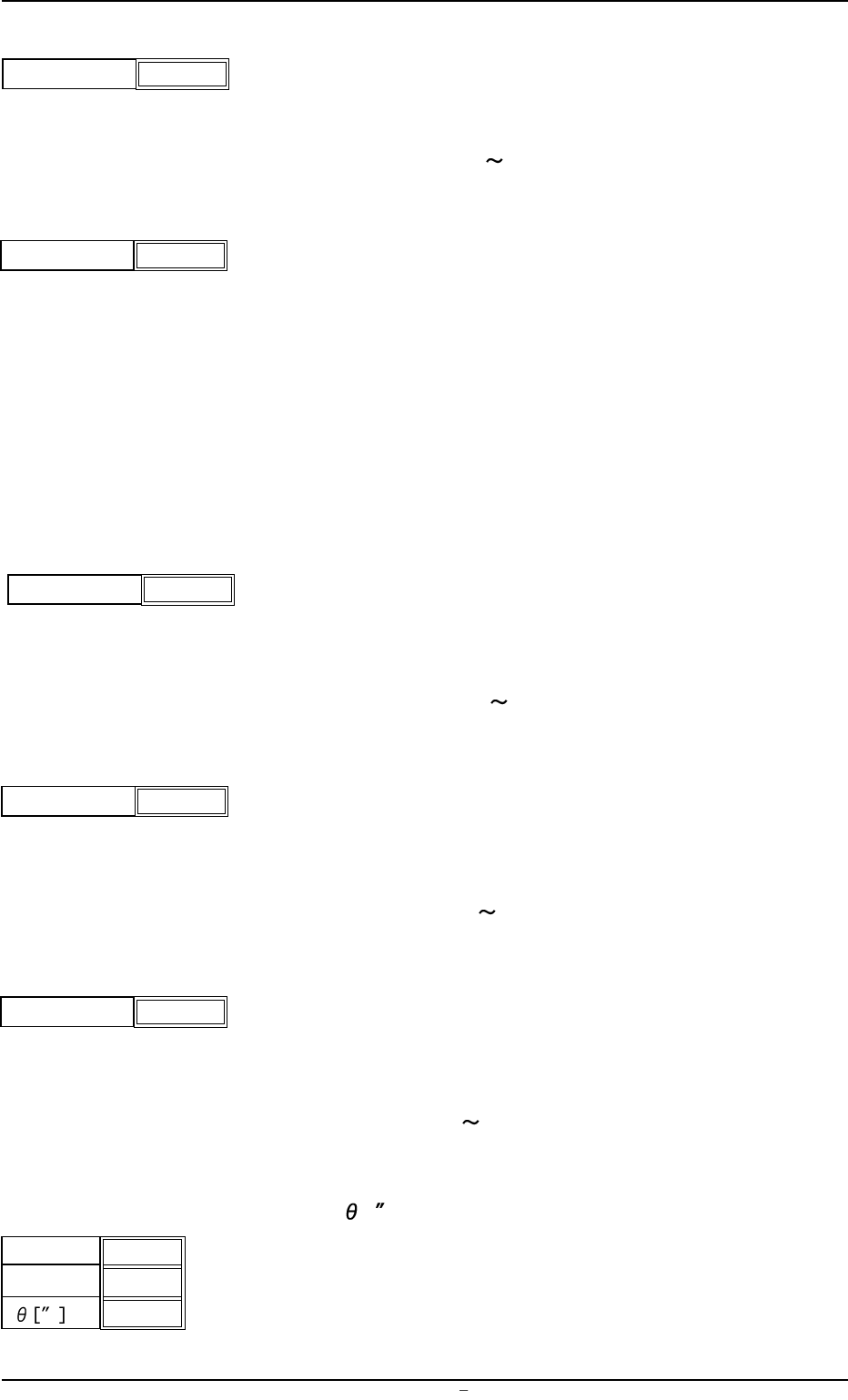
(12) Prntng. Correction (Back)
X [mm], Y [mm],
[ ]
Set parameters to correct the relative position (trace quantity) be-
tween the P.C.B. and the screen kept when the squeegees move
backward (from the front to the rear side).
X [mm]
Y [mm]
+ 0.000
+ 0.000
+ 0.000
Fig.3B19
Screen Distance
-0.1
Fig.3B14
1.2 Operation Data
0106-003 Chapter 1 2 5 AFU01EDTP
Separation Distance [mm]
0.5
Fig.3B18
Separation Acc. [mm/s
2
]
50.00
Fig.3B17
Separation Speed [mm/s]
0.05
Fig.3B16
Separation Mode PCB Down
Fig.3B15
(13) Prntng. Correction (For.)
X [mm], Y [mm],
[ ]
Set parameters to correct the relative position (trace quality) be-
tween the P.C.B. and the screen kept when the squeegees move
forward (from the rear to the front side).
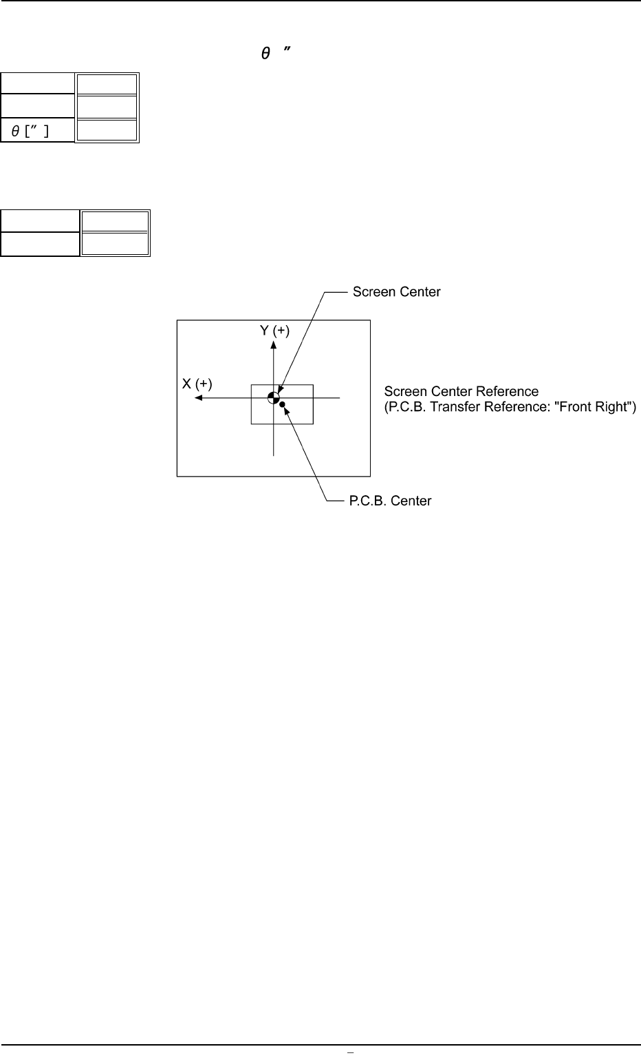
(14) Screen Offset [mm]
When the reference coordinates of the screen are changed from
the design values, set parameters as the offset values.
Unit: mm
Fig. 3B22
Data Input Range
X: ±5.0
Y: ±99
X [mm]
Y [mm]
+ 0.000
+ 0.000
+ 0000
Fig.3B20
1.2 Operation Data
0106-002 Chapter 1 2 6 AFU01EDTP
X
Y
Fig.3B21
+ 0.0
+ 00.0
1.2.3 PCB Backup
(1) Chuck Stage Select
Select the method to fix the P.C.B. on the table chute.
The specified data is used to determine the P.C.B. fixing method
of the P.C.B. positioning stage.
Backup Jig : This specifies the method which uses the backup
jig.
Backup Pin : This specifies the method which uses the P.C.B.
support pins.
Vacuum Plate : This specifies the vacuum pick-up system.
Select one of the options correctly according to the set-
tings of the mechanism section. Otherwise, the macine
will malfunction.
(2) PCB Warpage Protection
It can be selected whether or not the P.C.B. warpage protection
function should be used to correct the warpage of the P.C.B.
Select "ON" in normal cases.
When "OFF" is selected, transfer of overlapped P.C.B.’s
cannot be detected.
(3) Vacuum Release Mode
Select time when the picked P.C.B. should be released.
Before : The picked P.C.B. is released before printing operation.
After : The picked P.C.B. is released after printing operation.
Select "After" in normal cases.
When a P.C.B. has a lot of through holes and the machine per-
forms the printing operation with the P.C.B. being picked up, solder
paste may ooze out to the underside of the screen. In this case,
"Before" should be selected.
(4) Vacuum Rel. Wait Time [sec]
Set the waiting time during which the picked P.C.B. is released
and the backup table descends.
Unit: seconds
PCB Warpage Protection
ON
Fig.3B24
Vacuum Release Mode
Before
Fig.3B25
Fig.3B26
Vacuum Rel. Wait Time
[sec]
0.0
0004-001 Chapter 1 2 7 AFU01EDTP
1.2 Operation Data
Chuck Stage Select
Backup Jig
Fig.3B23