2OM-1104-001.pdf - 第270页
9.1.1 Adjustment of Squeegee Head Height • • • • • Rubber Squeegees Adjustment Procedure (1) Loosen the wing and stopper nuts. Fig. 5A37-1 (2) Adjust the pushing distance by changing Dimension L (the dis- tance between t…
9. Replacement of Consumables and Adjustment
9.1 Replacement of Squeegees
When the squeegee edge is worn out or deformed by solvent, etc.,
replace the squeegee with a new one to avoid any hindrance in printing.
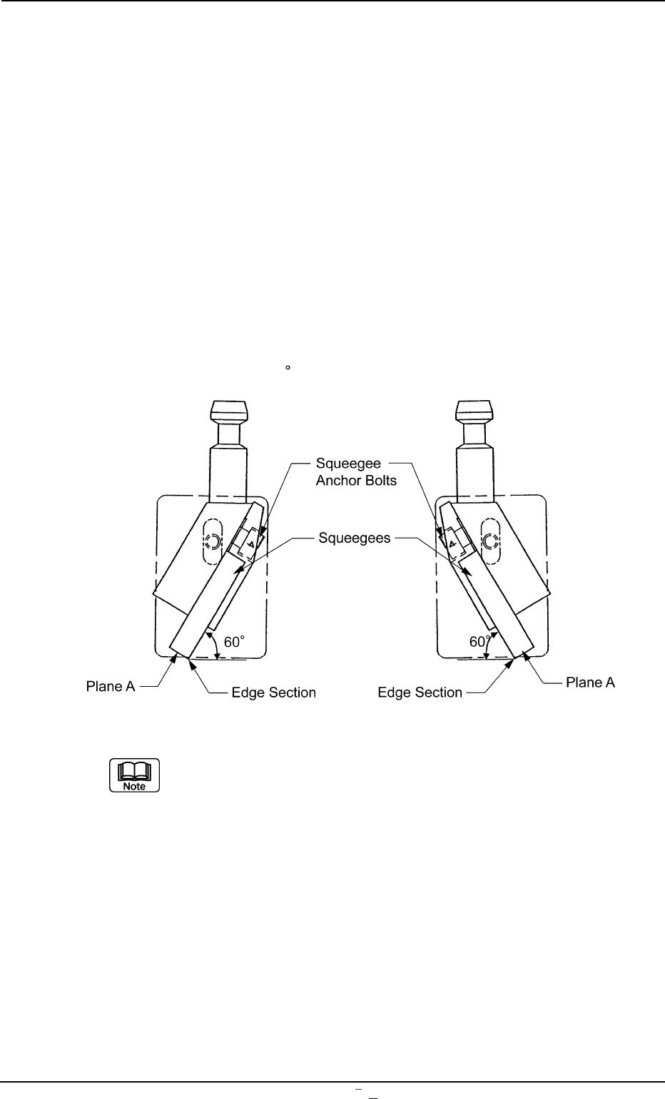
• Loosen the squeegee anchor bolt and detach the squeegee.
• Attach a new squeegee as shown in Fig. 5A37 and tighten the an-
chor bolt. At this time, be sure to push Plane A of the squeegee
against the flat surface such as a surface plate and tighten the bolt
evenly without any warpage.
• After tightening the bolt, put the edge against a flat surface to con-
firm that straightness is secured without any clearance.
The confirmation should be made with the squeegee pushed against
the surface plate at 60
(fixed).
Fig. 5A37
It is advisable that plane A should be polished with the squee-
gee being mounted to secure the straightness of the squee-
gee for good printing.
Especially, it is effective to print fine-pitched patterns and keep
the coating of the printed patterns in accurate shape.
0106-003 Chapter 3 1 31 AFU01EINP
9. Replacement of Consumables and Adjustment
9.1.1 Adjustment of Squeegee Head Height
••
••
• Rubber Squeegees
Adjustment Procedure
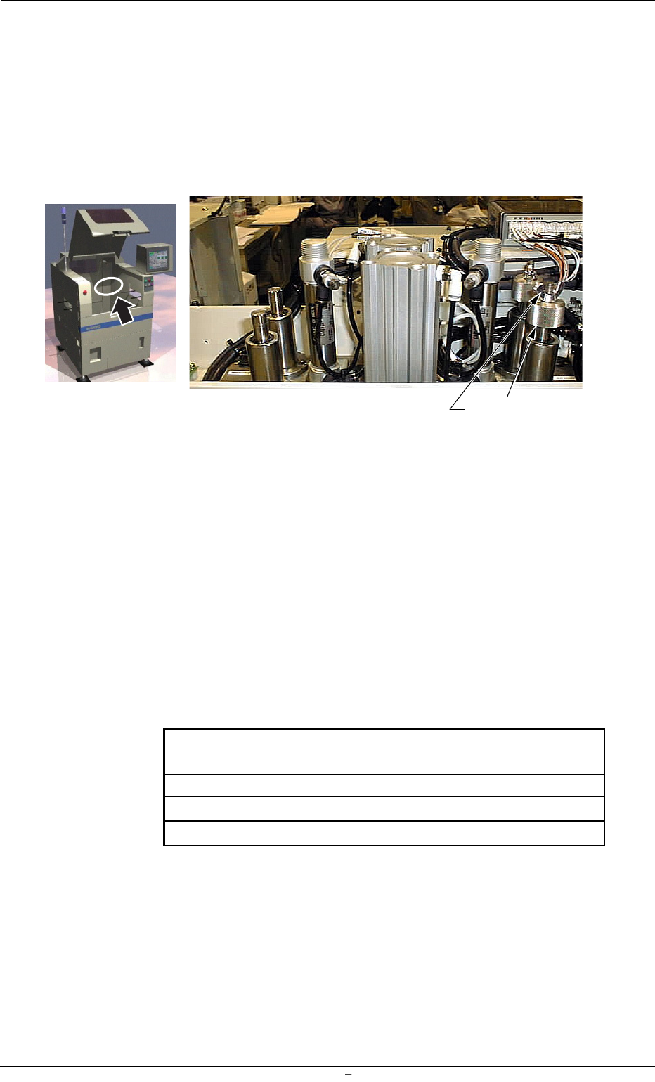
(1) Loosen the wing and stopper nuts.
Fig. 5A37-1
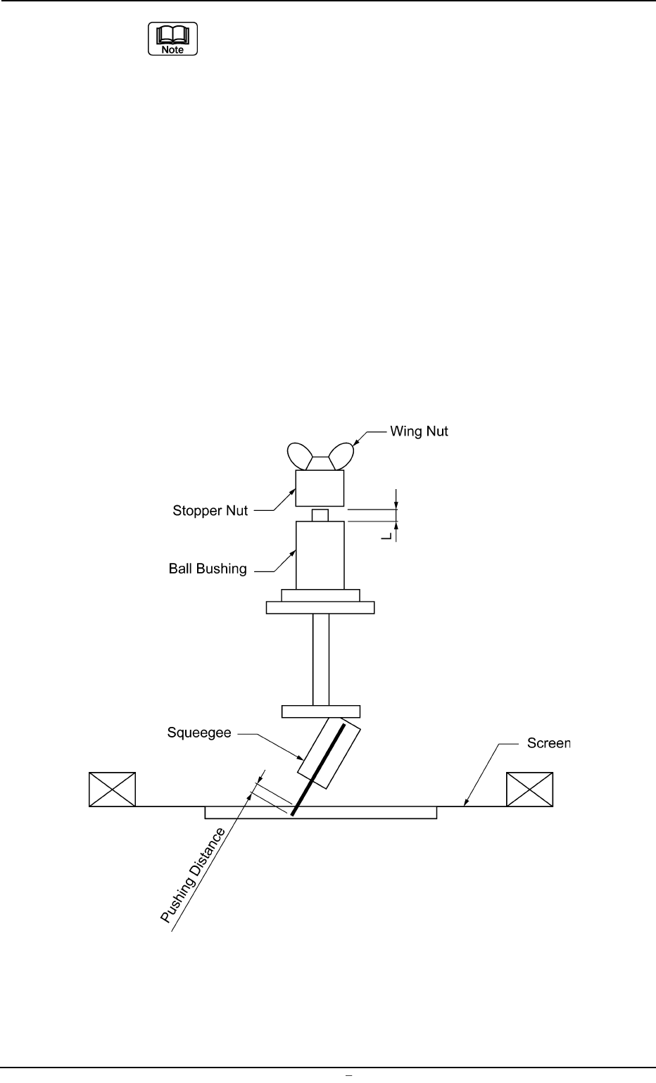
(2) Adjust the pushing distance by changing Dimension L (the dis-
tance between the upper end plane of the ball bushing and the
lower end plane of the stopper nut).
The pushing distance of the squeegee against the screen is set
to “1.0 mm”. (Factory-Adjusted upon Shipment)
When the stopper nut is turned once clockwise, the pushing
distance becomes shorter by 1.0 mm.
Turning the stopper nut once counterclockwise makes the push-
ing distance longer by 1.0 mm.
Ref.:
Pushing Distances Dimension L during Upward
Movement of Cylinder
0.5 mm 58.5 mm
1.0 mm 59.0 mm (Standard Setting)
1.5 mm 59.5 mm
(3) Open the “SEMI-AUTO OPN.” window (submenu) or the “Print
Block” tab sheet of the “MAN. SUB-SYS” window (submenu)
and push the squeegee against the P.C.B. located in the print-
ing section.
Refer to the above table and check the relation between Di-
mension L and the pushing distances.
Wing Nut
Stopper Nut
0106-002 Chapter 3 1 31-1 AFU01EINP
9.1 Replacement of Squeegees
(a) When the rubber squeegees are worn out, the push-
ing distance becomes as short as they are worn out.
Therefore, it is required to change the rubber squee-
gees before the pushing distance is changed greatly
(in the range of 0.5 mm or less).
(b) The rubber squeegees can be ground to be re-used.
In this case, the total of the dimension (grinding) is
limited to “1.5 mm” (when the maximum pushing dis-
tance is “0.5 mm”).
When the total of the dimension (grinding) has be-
come “1.5 mm”, be sure to replace the rubber squee-
gees with new ones.
(c) When the rubber squeegees are ground to be re-used,
lower the location of the stopper nuts according to
the dimensions of the ground rubber squeegees (the
squeegees that have become shorter after grinding)
so that the same pushing distances can be kept.
Fig. 5A37-2 Conceptualized Pushing Distance
0106-002 Chapter 3 1 31-2 AFU01EINP
9.1 Replacement of Squeegees