2OM-1104-001.pdf - 第27页
1.2.2 Print Data (1) Screen Basis Select a reference type of the screen frame. Center Ref. : The center of the screen frame is regarded as a reference point. Front Ref. : The front side of the screen frame is regarded as…
(3) Operation Mode
It can be selected whether or not solder paste should be printed
on the P.C.B. to be produced.
PRINT: The machine prints solder paste during automatic opera-
tion.
PASS : The machine pereforms only P.C.B. transfer during auto-
matic operation.
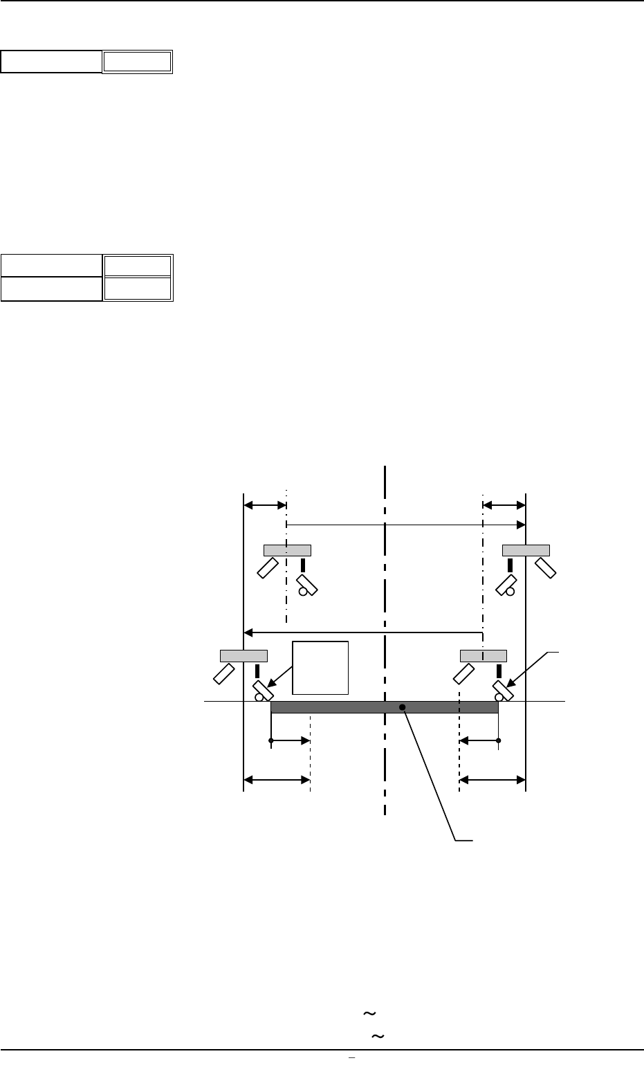
(4) Print Area
Set parameters as offset values of the P.C.B. end plane in the Y
direction.
Unit: mm
Enter the offset values based on the pattern program coodinates
of the end planes on the origin and rear sides. When the defaults
"0" (zero) are set, the whole area of the P.C.B. is printed.
Various offsets are considered in the actual printing range as shown
below.
L1, L2 : Printing Area Data (based on the pattern program origin)
X2 : Overshoot at End of Printing
S
o : Travel from Previous End Position at Printing Start (Squee-
gee Offset)
Fig.3B7
Data Input Range
Origin Side : -10 +250
Rear Side : -250
+10
Origin
Depth
+ 000.00
+ 000.00
Fig.3B6
1.2 Operation Data
0004-001 Chapter 1 2 3 AFU01EDTP
Operation Mode Print
Fig.3B5
Screen Center
S
o
S
o
Squeegee
L1
X2
(-)
P.C.B.
Pattern
Program
Origin
L1
X2
(+)
1.2.2 Print Data
(1) Screen Basis
Select a reference type of the screen frame.
Center Ref. : The center of the screen frame is regarded as a
reference point.
Front Ref. : The front side of the screen frame is regarded as a
reference point.
Rear Ref. : The rear side of the screen frame is regarded as a
reference point.
(2) Round-Way Printing
It can be selected whether or not the round-way printing operation
should be performed.
ON : The machine performs the round-way printing operation.
OFF: The machine does not perform the round-way printing op-
eration.
(3) Frame Select
Select dimensions of the screen frame to be used.
Unit: mm
650
××
××
×550
550
××
××
×550 600
××
××
×550 550
××
××
×650
(4) Prntg. Press. [N]
Set the printing pressures of the front and rear squeegees.
Unit: N
Data Input Range: 10
147 N
(5) Squeegee Select
Select the length ("270" or "350") of the squeegee to be used.
Unit: mm
(6) Squeegee Spd.
Select the speed at which the squeegees move back and forth for
printing.
Unit: mm/s
For. : Set the speed at which the squeegees move forward (from
the rear to the front side).
Back. : Set the speed at which the squeegees move backward
(from the front to the rear side).
Front Side
Rear Side
040
040
Fig.3B11
005
005
0009-002 Chapter 1 2 4 AFU01EDTP
1.2 Operation Data
Fig.3B8
Screen Basis
Center Ref.
Round-Way Printing
OFF
Fig.3B9
Frame Select
650 550
Fig.3B10
Squeegee Select
270
Fig.3B12
FOR.
BACK
Fig.3B13
(7) Screen Distance
Set the clearance between the screen and the upper surface of
the P.C.B. during printing operation.
Unit: mm
Data Input Range: -1.5 3.0
(8) Separation Mode
Set a parameter to determine whether or not the squeegees must
move up after the P.C.B. has descended or the P.C.B. must move
down after the squeegees have ascended when the screen frame
is separated from the P.C.B. after the completion of printing.
PCB Down : The squeegees move up after the P.C.B. has
descended.
Squeegee Up : The P.C.B. moves down after the squeegees
have ascended.
(9) Separation Speed [mm/s]
Set the speed at which the screen frame should be separated from
the P.C.B. after the end of printing.
Unit: mm/s
Data Input Range: 0.05
3.00
(10) Separation Acc. [mm/s
2
]
Set the acceleration rate at which the screen frame should be sepa-
rated from the P.C.B. after the end of printing.
Unit: mm/s
2
Data Input Range: 0.1 50.0
(11) Separate Distance [mm]
Set the distance of the screen frame to be kept when it is sepa-
rated from the P.C.B. after the end of printing.
Unit: mm
Data Input Range: 0
9.9
(12) Prntng. Correction (Back)
X [mm], Y [mm],
[ ]
Set parameters to correct the relative position (trace quantity) be-
tween the P.C.B. and the screen kept when the squeegees move
backward (from the front to the rear side).
X [mm]
Y [mm]
+ 0.000
+ 0.000
+ 0.000
Fig.3B19
Screen Distance
-0.1
Fig.3B14
1.2 Operation Data
0106-003 Chapter 1 2 5 AFU01EDTP
Separation Distance [mm]
0.5
Fig.3B18
Separation Acc. [mm/s
2
]
50.00
Fig.3B17
Separation Speed [mm/s]
0.05
Fig.3B16
Separation Mode PCB Down
Fig.3B15