2OM-1104-001.pdf - 第24页
Section 2 Pattern Program 0004-001 Chapter 1 2 1 AFU01EDTP This section describes the contents and editing of the pattern program.
1.3.3 Device Data
The device data is composed of the following data.
Refer to "3. "Device Data" Submenu" in "Section 4 Menus for System
Setting" for details.
Table 3A13
Data Item Referential Items
Input Mode 3 in
4
Output Mode 3 in
4
Hold P.C.B. 3 in
4
PCB Input Speed 3 in
4
Auto Run/Stop 3 in
4
Timer Setting (sec) 3 in
4
Conveyor Speed Down Offset 3 in
4
1.3.4 Offset Data
The offet data is composed of the following data.
Refer to "4. "Offset Data" Submenu" in "Section 4 Menus for System
Setting" for details.
Table 3A14
Data Item Referential Items
Machine Offset 4.1 in
4
P.E.C. Recognition Camera 4.2 in
4
Screen Recognition Camera 4.3 in
4
0009-002 Chapter 1 1 8 AFU01EDTP
1.3 Various Data

Section 2
Pattern Program
0004-001 Chapter 1 2 1 AFU01EDTP
This section describes the contents and editing of the
pattern program.
1. Pattern Program
1.1 Model Name
When a pattern program should be saved, up to 8 characters (alphanumerics
and symbols) can be used as a pattern program name.
1.2 Operation Data
1.2.1 P.C.B. Data
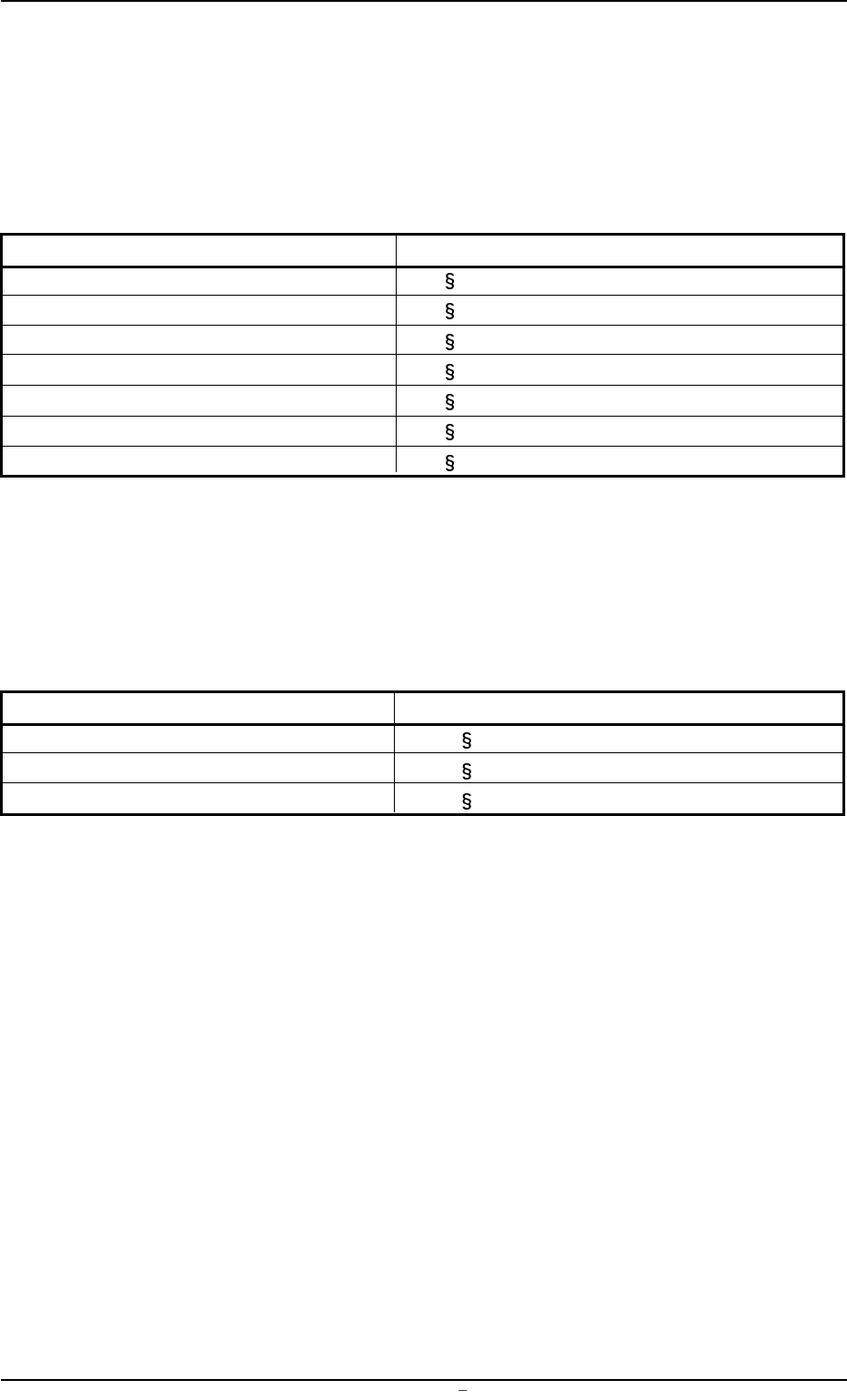
(1) P.C.B. Size
X (horizontal), Y (vertical), and T (thickness)
Set the dimensions of the P.C.B. to be produced.
Unit: mm
Fig. 3B2
Data Input Range
X: 50
330 Y: 35 250 T: 0.5 5.0
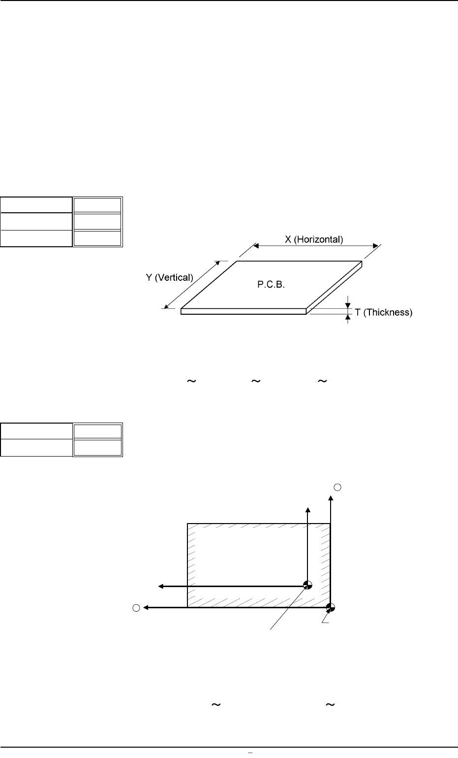
(2) P.C.B. Origin OFfset
X (horizontal) and Y (vertical)
Set the offset values to correct the difference between the refer-
ence point (N
0
) of the pattern program and the P.C.B. origin (P
0
) .
Unit: mm
Fig. 3B4
Data Input Range
X: -99.999
+99.999 Y: -99.999 +99.999
X
Y
000.00
000.00
T
2.00
Fig.3B1
X
Y
+00.000
+00.000
Fig.3B3
P
0
(P.C.B. Origin)
Y +
X +
P.C.B.
N
0
(Printing Coordinates Reference)
1.1 Model Name
0004-001 Chapter 1 2 2 AFU01EDTP