2OM-1104-001.pdf - 第32页
1.2.4 P .E.C. Recognition (1) P .E.C. Recog. Function It can be selected whether or not the P .E.C. recognition function should be used. 2PT . : The machine performs the tow-point recognition. OFF : The machine does not …
(5) PCB Clamp Offset
The backup table ascends to the position where a P.C.B. is chucked.
It starts ascending again after the P.C.B. horizontal clamping unit
has chucked the P.C.B.
When thin P.C.B.’s are used and chuck errors occur, enter a value
as timing with which a P.C.B. is chucked and the backup table
starts ascending again and a value that represents the position
where the P.C.B. horizontal clamping unit starts to chuck the P.C.B.
Timing [sec] : Enter a value that represents the timing
with which the backup starts ascending
again after it has stopped.
Unit: seconds
Position [mm] : Enter a value that represents the
changed dimension based on the cur-
rent position.
Unit: mm
When a minus (-) value is entered, the
height for chucking start can be changed.
Bef.Clamp Bkup Spd. : The ascending speed of the backup table
can be set in the range of 10 steps (Full
Speed to 90 Down) before the P.C.B.
is clamped.
Unit: %
Aft.Clamp Bkup Spd. : The ascending speed of the backup table
can be set in the range of 10 steps (Full
Speed to
90 Down) after the P.C.B. is clamped.
Unit: %
(6) P.C.B. Stopper Offset Y [mm]
Set the offset in the Y direction of the stopper that is used to stop
the P.C.B. in the table chute section.
Unit: mm
When the offset is "0" (zero), the P.C.B. stopper is located at the
center of the P.C.B. end plane.
Specify the offset when there is a cutout, etc., at the center of the
P.C.B. end plane.
(7) PCB Cut Offset [mm]
When the P.C.B. has a cutout at its edge and must be positioned
against the P.C.B. stopper, enter the depth of the cutout in the text
box.
Unit: mm
0106-003 Chapter 1 2 8 AFU01EDTP
1.2 Operation Data
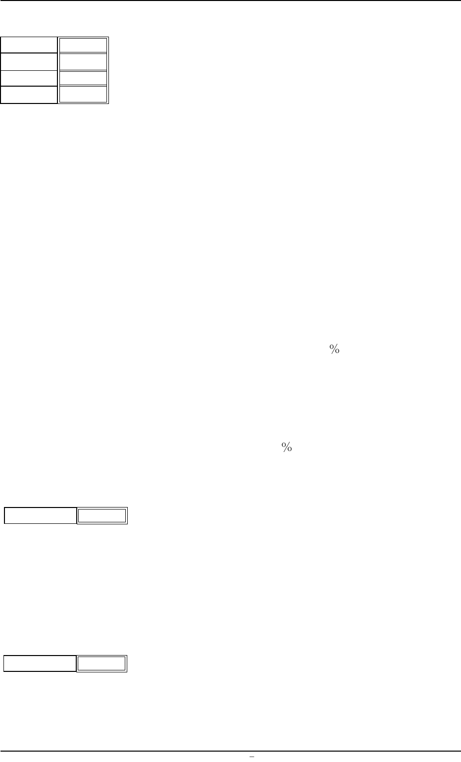
Fig.3B27
Timing [sec]
Position [mm]
0.00
+0.0
P.C.B. Stopper Offset Y
[mm]
+000
Fig.3B28
P.C.B. Cut Offset [mm]
000
Fig.3B28-1
Bef.Clamp
Bkup Spd.
Aft.Clamp
Bkup Spd.
Full Speed
Full Speed
1.2.4 P.E.C. Recognition
(1) P.E.C. Recog. Function
It can be selected whether or not the P.E.C. recognition function
should be used.
2PT. : The machine performs the tow-point recognition.
OFF : The machine does not perform the P.E.C. recognition.
One of the options ("OFF", "1PT.", "2PT.", and "3PT.")
can be selected. However, the machine perform the rec-
ognition only when "2PT." is selected.
(2) Center Recognition
It can be selected whether or not the machine should perform the
center recognition.
ON : The machine performs the center recognition.
OFF : The machine does not perform the center recognition.
When the center recognition function is used, a fiducial mark is
recognized once and the camera is moved to the position where
the recognized fiducial mark is located at the center of the visual
field. After that, the fiducial mark is re-recognized.
The positional accuracy is improved because the mark is recog-
nized at the center of the visual field (the spot of the lens with less
distortion).
(3) Fiducial Mark #1
X [horizontal] and Y [vertical]
Set the coordinates of the first fiducial mark.
Unit: mm
Code
Set the code No. of the first fiducial mark.
(4) Fiducial Mark #2
X [horizontal] and Y [vertical]
Set the coordinates of the second fiducial mark.
Unit: mm
Code
Set the code No. of the second fiducial mark.
PEC Recog. Function
OFF
Fig.3B30
Center Recognition
OFF
Fig.3B31
0004-001 Chapter 1 2 9 AFU01EDTP
1.2 Operation Data
X (Horizontal)
Y (Vertical)
000.000
000.000
Code
01
Fig.3B32
X (Horizontal)
Y (Vertical)
000.000
000.000
Code
01
Fig.3B33
(5) Recog. Adjust Correct
It can be selected whether or not the recognition adjustment point
(the center point to correct positional deviation between the P.C.B.
and the screen frame) should be specified to correct the align-
ment of the P.C.B. with the screen.
ON : The specified parameters in the "Recog. Adjust Point X"
and "Recog. Adjust Point Y" text boxes become the recog-
nition adjustment point.
OFF : The P.C.B. center is automatically specified as the recog-
nition adjustment point.
(6) Recog. Adjust Point X (horizontal) and Y (vertical)
Set coordinates as the recognition adjustment point to correct the
alignment of the P.C.B. with the screen.
Unit: mm
The specified parameters become valid only when "ON" is set in
the "Recog. Adjust Correct" text box.
0004-001 Chapter 1 2 10 AFU01EDTP
1.2 Operation Data
000.00
000.00
X (Horizontal)
Y (Vertical)
Fig.3B35
Recog. Adjust Correct
OFF
Fig.3B34