2OM-1104-001.pdf - 第274页
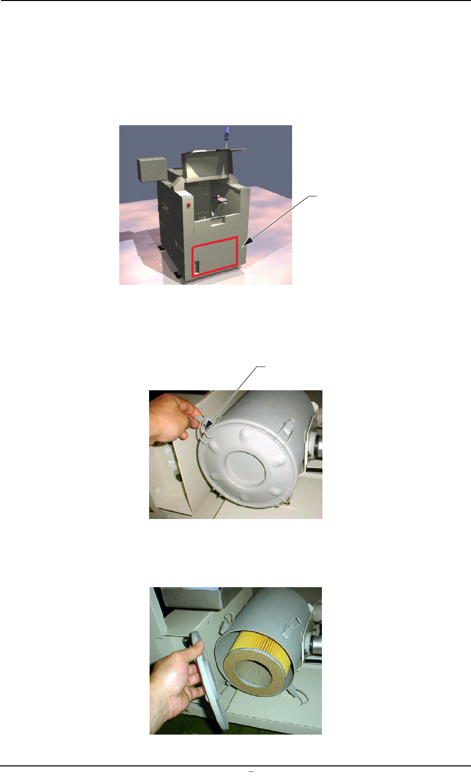
9.2 Replacement Procedure of Blower Filter Operation Procedure (1) Remove the cover located at the lower part of the rear side. (4 screws) Fig. 5A37-6 (2) Disengage the clip fastening the lid of the filter cover . (4 pla…
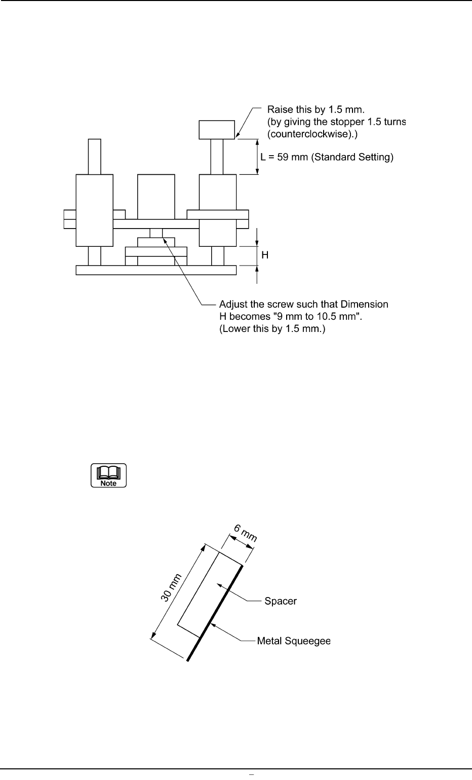
Adjustment Procedure (Spacers Not Used)
(1) Give the pushing stopper 1.5 turns (counterclockwise) to raise it by
1.5 mm.
(2) Loosen the screw located at the end of the squeegee up/down
cylinder to lower the squeegee by 1.5 mm.
Fig. 5A37-4
• Metal Squeegees without Holders (Separated from Holders)
When a spacer is made of urethane rubber, etc., as shown below, keeping the
same dimensions as the rubber squeegees, the pushing distance can be ad-
justed in the same way as the rubber squeegees.
When a spacer is made based on the different dimensions (other than
the above-described ones), the squeegee head position must be ad-
justed according to the dimensions.
Fig. 5A37-5
0106-001 Chapter 3 1 31-4 AFU01EINP
9.1 Replacement of Squeegees
9.2 Replacement Procedure of Blower Filter
Operation Procedure
(1) Remove the cover located at the lower part of the rear side.
(4 screws)
Fig. 5A37-6
(2) Disengage the clip fastening the lid of the filter cover.
(4 places)
Fig. 5A37-7
(3) Remove the lid.
Fig. 5A37-8
9.2 Replacement Procedure of Blower Filter
Cover
Clip
0106-001 Chapter 3 1 31-5 AFU01EINP
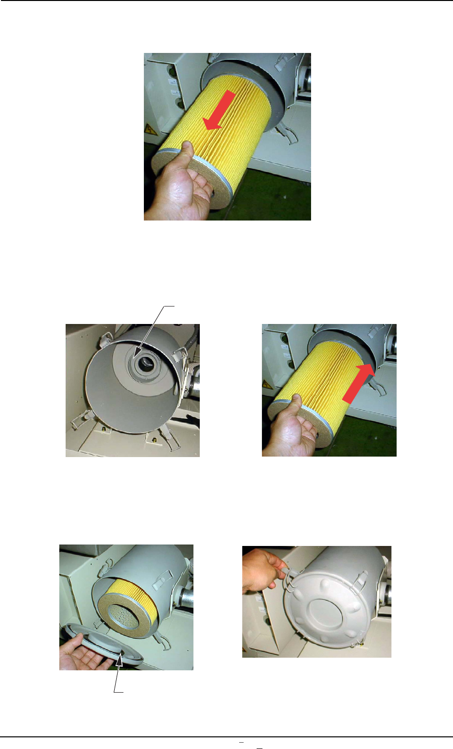
(4) Detach the filter and remove dust accumulated on the filter with an
air gun and a vacuum cleaner.
Fig. 5A37-9
(5) Set the filter such that the center hole of the filter can fit into the
flange located at the rear side of the filter cover.
Fig. 5A37-10
(6) While holding the lid, engage the clip securely such that the flange
(located at the center of the lid) can fit into the center hole of the
filter.
Fig. 5A37-11
9.2 Replacement Procedure of Blower Filter
0106-001 Chapter 3 1 31-6 AFU01EINP
Flange Section
Flange Section