2OM-1104-001.pdf - 第275页
(4) Detach the filter and remove dust accumulated on the filter with an air gun and a vacuum cleaner . Fig. 5A37-9 (5) Set the filter such that the center hole of the filter can fit into the flange located at the rear si…
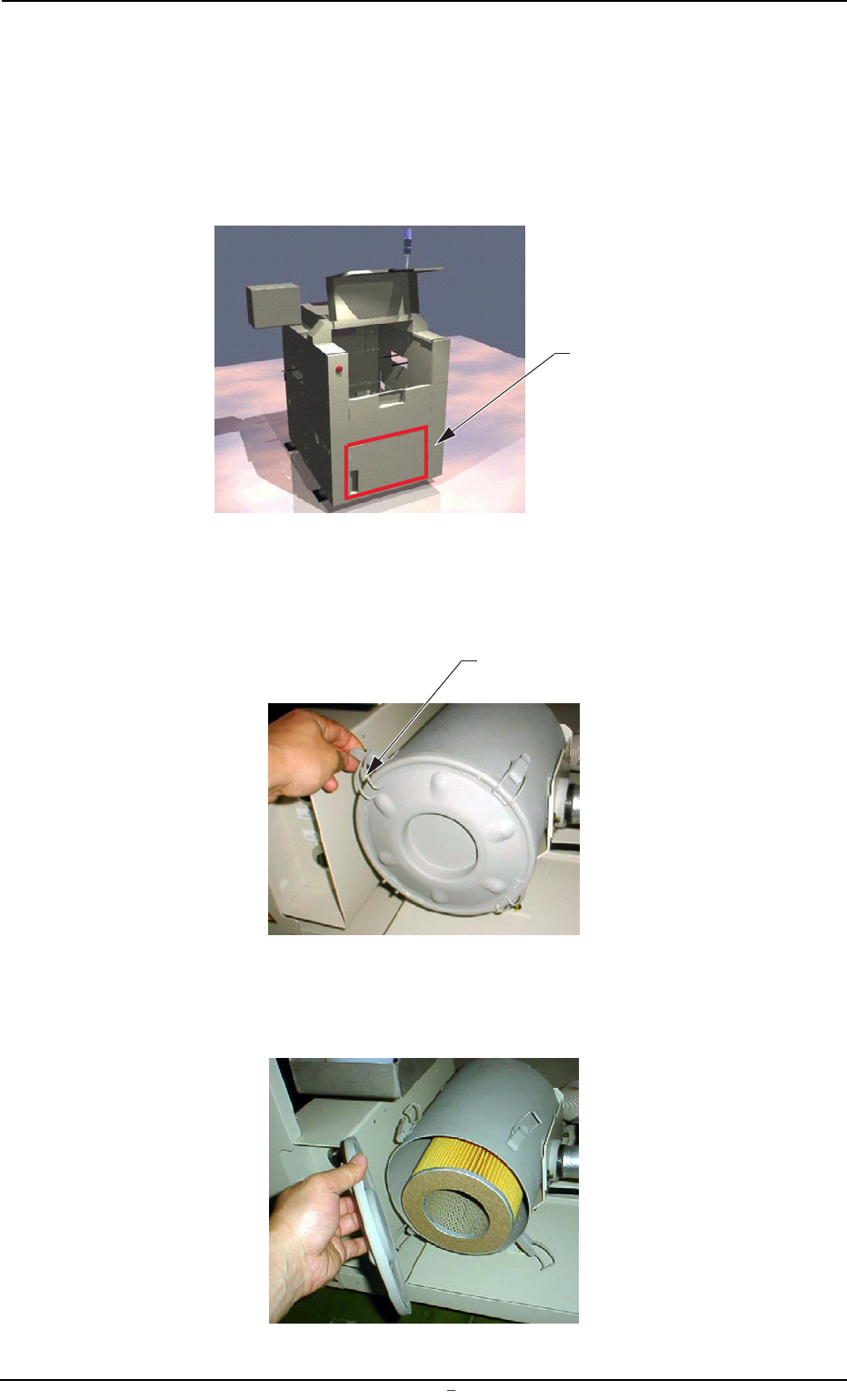
9.2 Replacement Procedure of Blower Filter
Operation Procedure
(1) Remove the cover located at the lower part of the rear side.
(4 screws)
Fig. 5A37-6
(2) Disengage the clip fastening the lid of the filter cover.
(4 places)
Fig. 5A37-7
(3) Remove the lid.
Fig. 5A37-8
9.2 Replacement Procedure of Blower Filter
Cover
Clip
0106-001 Chapter 3 1 31-5 AFU01EINP
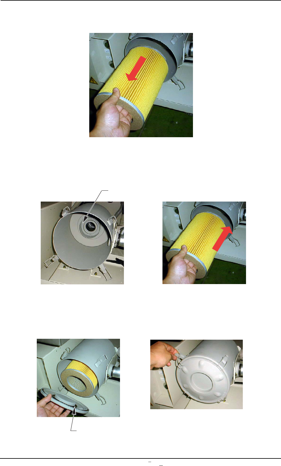
(4) Detach the filter and remove dust accumulated on the filter with an
air gun and a vacuum cleaner.
Fig. 5A37-9
(5) Set the filter such that the center hole of the filter can fit into the
flange located at the rear side of the filter cover.
Fig. 5A37-10
(6) While holding the lid, engage the clip securely such that the flange
(located at the center of the lid) can fit into the center hole of the
filter.
Fig. 5A37-11
9.2 Replacement Procedure of Blower Filter
0106-001 Chapter 3 1 31-6 AFU01EINP
Flange Section
Flange Section
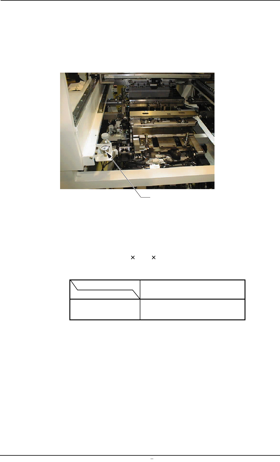
10. Adjustment of P.C.B. Horizontal Clamping
When a thin P.C.B. is used and the horizontal clamping force is strong,
it may be warped. To avoid this, adjust the force with the pressure re-
ducing valve which is located at the front left (operator side) of the L
conveyor.
Fig. 5A38
• Refer to the following table for the relation between the P.C.B. thick-
ness and air pressure.
The values indicate the pressures to be applied, assuming that a
P.C.B. (Dimensions: "150
100 1.5 (t)") is used without a P.C.B.
stopper.
P.C.B. Thickness
Air Pressure 0.5 1.0 1.5 2.0 (mm)
MPa 0.12 0.2 0.3 0.3
(kgf/cm
2
) (1.2) (2.0) (3.0) (3.0)
0009-002 Chapter 3 1 32 AFU01EINP
10. Adjustment of P.C.B. Horizontal Clamping
Pressure Reducing Valve