2OM-1104-001.pdf - 第345页
0106-002 Chapter 3 3 50 AFU01EMTP 3.3 Location of Sensors for P .E.C. Recognition 3.3 Location of Sensors for P .E.C. Recognition Fig. 5C6
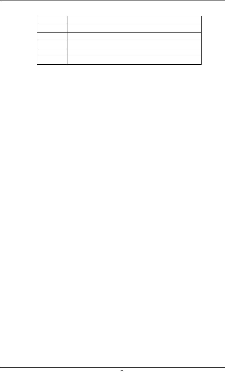
Table 5C4
Symbols Name
MPM023 P.C.B. U/D Pulse Motor
MPM025 Pulse Motor for Rail Width Adjustment
SVS052 Pressure Switch
YSV058 P.C.B. Horizontal Clamping Solenoid Valve (Outward)
YSV059 P.C.B. Horizontal Clamping Solenoid Valve (Backward)
0106-002 Chapter 3 3 49 AFU01EMTP
3.2 Location of Sensors in Table Section
0106-002 Chapter 3 3 50 AFU01EMTP
3.3 Location of Sensors for P.E.C. Recognition
3.3 Location of Sensors for P.E.C. Recognition
Fig. 5C6
0106-002 Chapter 3 3 51 AFU01EMTP
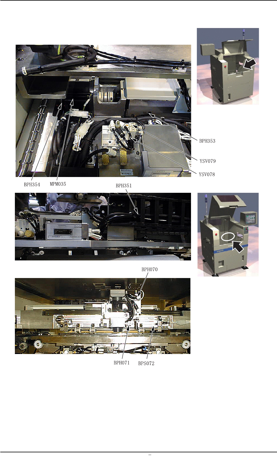
Fig. 5C7
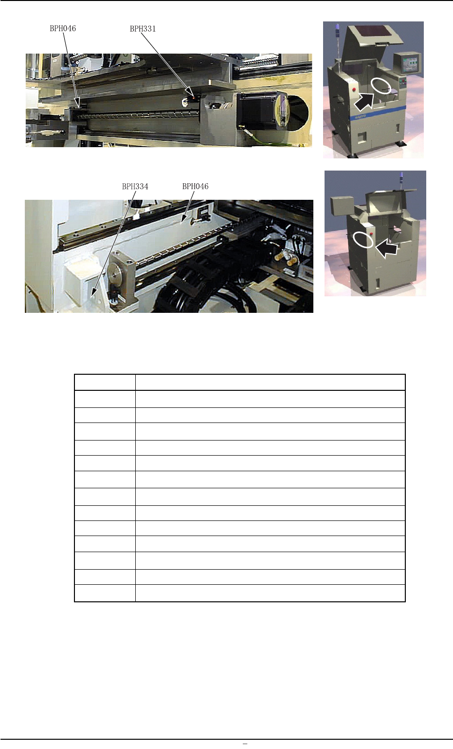
Table 5C4
Symbols Name
BPH046 P.C.B. Recognition Y-Axis Interlock
BPS070 P.C.B. Stopper Upper Limit
BPH071 P.C.B. Check
BPH072 (Overlapped P.C.B. Detection)
BPH331 P.E.C. Recognition Y-Axis Origin
BPH334 P.E.C. Recognition Y-Axis Rotational Origin
BPH351 P.E.C. Recognition X-Axis Origin
BPH353 P.E.C. Recognition X-Axis Limit (-)
BPH354 P.E.C. Recognition X-Axis Rotational Origin
MPM035 P.E.C. Recognition X-Axis Pulse Motor
MPM033 P.E.C. Recognition Y-Axis Pulse Motor
YSV078 P.C.B. Warpage Top Holding Upper Limit Solenoid Valve
YSV079 P.C.B. Stopper Solenoid Valve
3.3 Location of Sensors for P.E.C. Recognition