2OM-1104-001.pdf - 第273页
Adjustment Procedure (Spacers Not Used) (1) Give the pushing stopper 1.5 turns (counterclockwise) to raise it by 1.5 mm. (2 ) Loosen the screw located at the end of the squeegee up/down cylinder to lower the squeegee by …
• Metal Squeegees with Holders (Incorporated with Holders)
Example : Permalex: PLX-A3060-270, PLX-A3060-350
When the metal squeegees are attached with the same
settings as the rubber squeegees, the clearances be-
tween the squeegees and the screen are changed in
the height direction because the blades are located at
the center of the holder thickness, making the push-
ing distances insufficient. Therefore, it is required to
adjust the pushing distances.
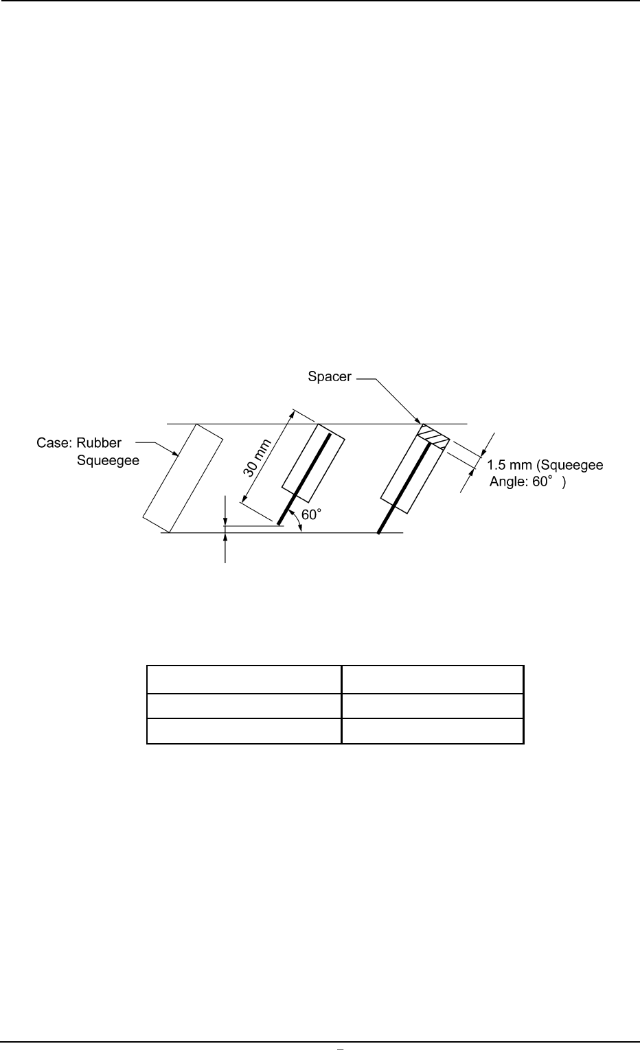
Adjustment Procedure for Spacer Use
(1) When spacers (thickness: 1.5 mm) are inserted as shown be-
low before the metal squeegees are attached to the squeegee
holders, the pushing distances can be kept to “1.0 mm” (same
as the rubber squeegees). (Squeegee Angle: 60°, Squeegee
Height: 30 mm)
Fig. 5A37-3
Refer to the table below before purchasing spacers.
Spacer Length Part No.
270 mm 630 097 6656
350 mm 630 097 6663
0106-001 Chapter 3 1 31-3 AFU01EINP
9.1 Replacement of Squeegees
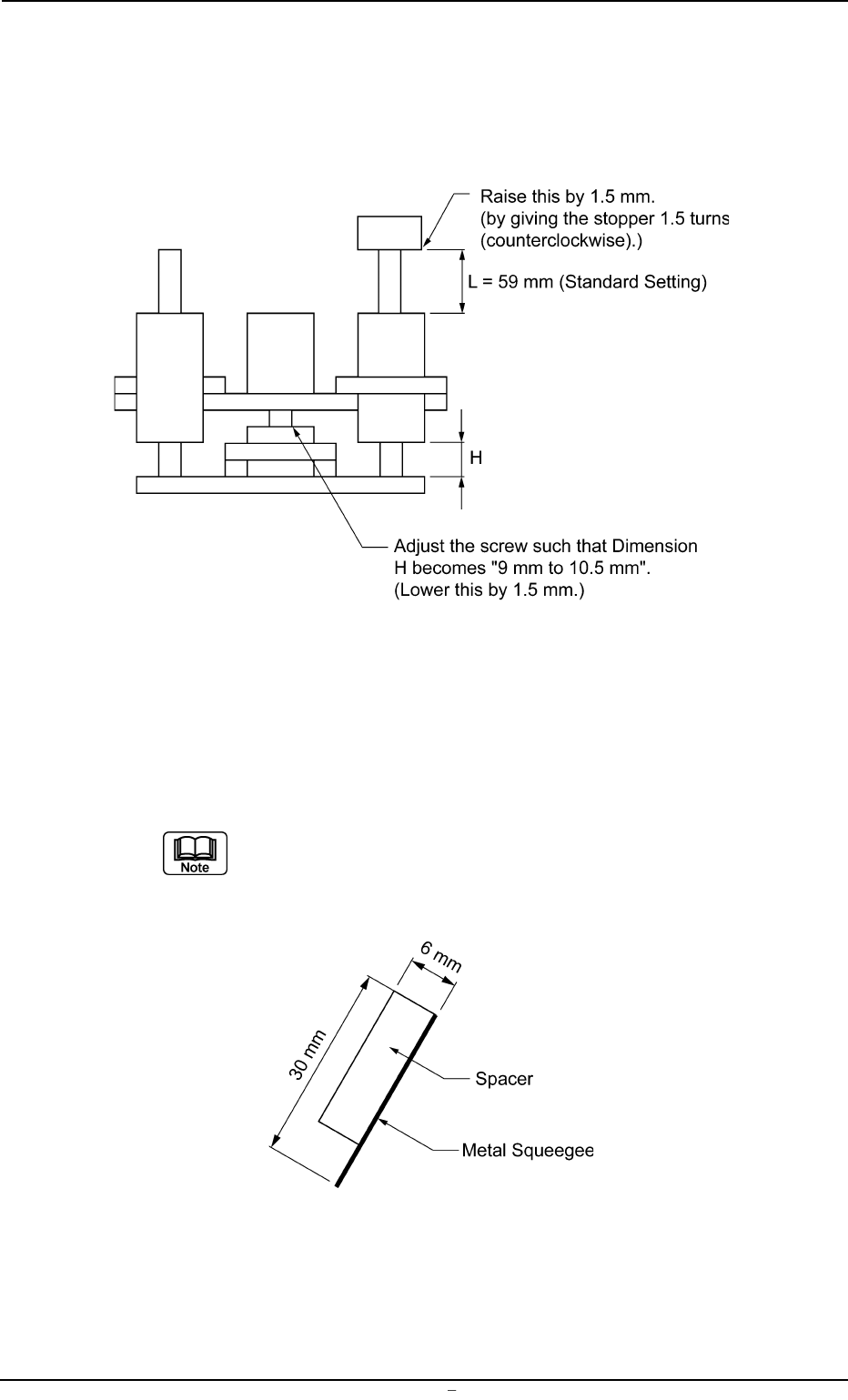
Adjustment Procedure (Spacers Not Used)
(1) Give the pushing stopper 1.5 turns (counterclockwise) to raise it by
1.5 mm.
(2) Loosen the screw located at the end of the squeegee up/down
cylinder to lower the squeegee by 1.5 mm.
Fig. 5A37-4
• Metal Squeegees without Holders (Separated from Holders)
When a spacer is made of urethane rubber, etc., as shown below, keeping the
same dimensions as the rubber squeegees, the pushing distance can be ad-
justed in the same way as the rubber squeegees.
When a spacer is made based on the different dimensions (other than
the above-described ones), the squeegee head position must be ad-
justed according to the dimensions.
Fig. 5A37-5
0106-001 Chapter 3 1 31-4 AFU01EINP
9.1 Replacement of Squeegees
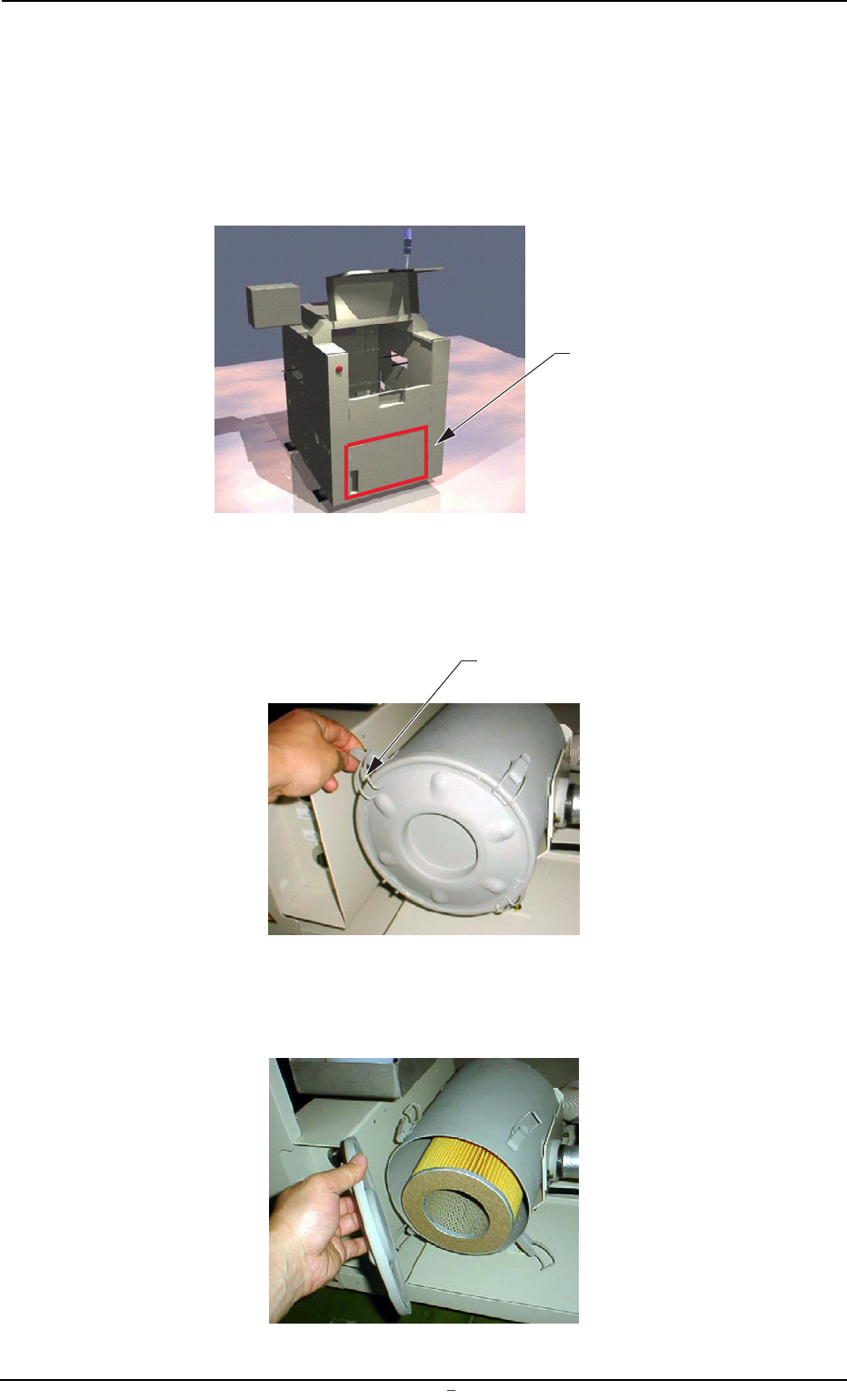
9.2 Replacement Procedure of Blower Filter
Operation Procedure
(1) Remove the cover located at the lower part of the rear side.
(4 screws)
Fig. 5A37-6
(2) Disengage the clip fastening the lid of the filter cover.
(4 places)
Fig. 5A37-7
(3) Remove the lid.
Fig. 5A37-8
9.2 Replacement Procedure of Blower Filter
Cover
Clip
0106-001 Chapter 3 1 31-5 AFU01EINP