2OM-1104-001.pdf - 第84页
*4 Printing Time This indicates the cumulative period of time during which printing operations were actually performed (from the start to the end). The cumulative period of time does not include the peri- ods of time dur…
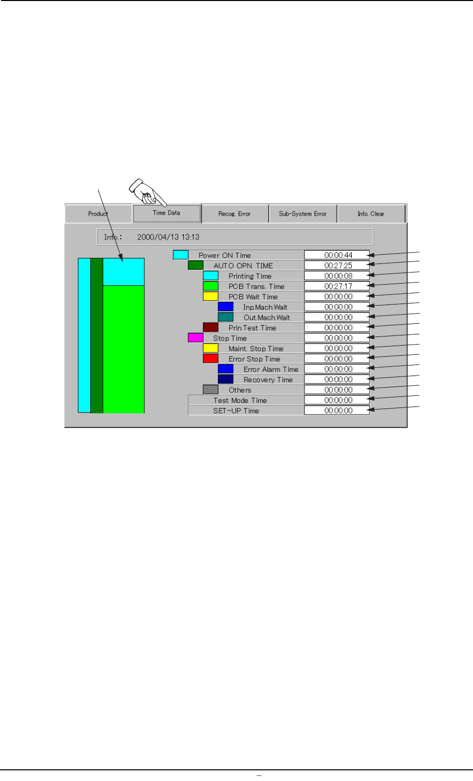
2.2 "Time Data" Tab
Displayed is the data that represents the cumulative periods of running
time for each operation mode.
• Sheet Layout
When the "Time Data" tab is pressed in the "MANAGE. DATA 1" win-
dow (submenu), the following tab sheet appears.
Fgi. 3C5 "Time Data" Tab Sheet
• Sheet Composition
*1 Ratio Chart of Operation Time
Each time ratio based on "Power ON Time" (described below in *2)
is classified by colors and charted by columns. The colors in the
chart correspond to those indicated before each name.
Each time ratio is updated every 5 seconds.
*2 Power ON Time
This indicates the cumulative period of time ("*3 AUTO OPN. TIME"
+ "*10 Stop Time") during which the control power was ON.
*3 AUTO OPN. TIME
This indicates the cumulative period of time ("*4 Printing Time" +
"*5 PCB Trans. Time" + "*6 PCB Wait Time" + "*9 Print. Test Time")
during which the object P.C.B.’s were produced.
0004-001 Chapter 1 3 8 AFU01EDTP
2.2
"
Time Data
"
Tab
*1
*2
*3
*4
*5
*6
*7
*8
*9
*10
*11
*12
*13
*14
*15
*16
*17
*4 Printing Time
This indicates the cumulative period of time during which printing
operations were actually performed (from the start to the end).
The cumulative period of time does not include the peri-
ods of time during which the machine is in the "STOP" or
the "PAUSE" mode, the semi-auto operation is performed,
or P.C.B.’s are transferred.
*5 PCB Trans. Time
This indicates the cumulative period of time during which the P.C.B.
transfer motors for the R and L conveyors were activated.
The cumulative period of time does not include the print-
ing time.
*6 PCB Wait Time
This indicates the cumulative period of time ("*7 Inp. Mach. Wait" +
"*8 Out. Mach. Wait") during which the main machine was waiting
for the input and output machines to transfer or discharge a P.C.B.
*7 Inp. Mach. Wait
This indicates the cumulative period of time during which the main
machine was waiting for the input machine to transfer a P.C.B.
*8 Out. Mach. Wait
This indicates the cumulative period of time during which the main
machine was waiting for the output machine to discharge a P.C.B.
*9 Prin. Test Time
Displayed is the time required to inspect the printing condition of
the P.C.B. This printing condition inspection function is optional.
When the machine is not provided with this function, “0” (zero) will
be set in the “Prin. Test Time” text box.
*10 Stop Time
This indicates the cumulative period of time ("*11 Maint. Stop Time"
+ "*12 Error Stop Time" + "*15 Others") during which the machine
was stopped.
*11 Maint. Stop Time
This indicates the period of time during which the machine was
stopped for the following maintenance operations.
• Manual Cleaning of Screen
• Replenishment of Cleaning Solvent
• Replenishment of Cleaning Paper
• Replenishment of Solder Paste
0106-003 Chapter 1 3 9 AFU01EDTP
2.2
"
Time Data
"
Tab

*12 Error Stop Time
This indicates the period of time ("*13 Error Alarm Time" + "*14
Recovery Time") during which the machine was reset to its normal
condition after an error alarm was issued.
*13 Error Alarm Time
This indicates the period of time during which the machine issued
an error alarm.
*14 Recovery Time
This indicates the period of time required for the machine to be
reset to its normal condition.
*15 Others
This indicates the period of time required for setup, program change,
and idling operations.
*16 Test Mode Time
This indicates the period of time during which the machine was
operated in the "TEST" mode (operation mode).
*17 SET-UP Time
This indicates the period of time during which the [OPERATION/
SET UP] switch on the front operation panel was set to the "SET
UP" side.
0106-002 Chapter 1 3 10 AFU01EDTP
2.2
"
Time Data
"
Tab