2OM-1104-001.pdf - 第127页
Input Conveyor : Enter an offset value based on the specified one (2.0 mm) as a clearance (dimension) in the X direction of the terminal area between the L conveyor and the table chute. Fig. 3D13-1 Output Conveyor : Ente…
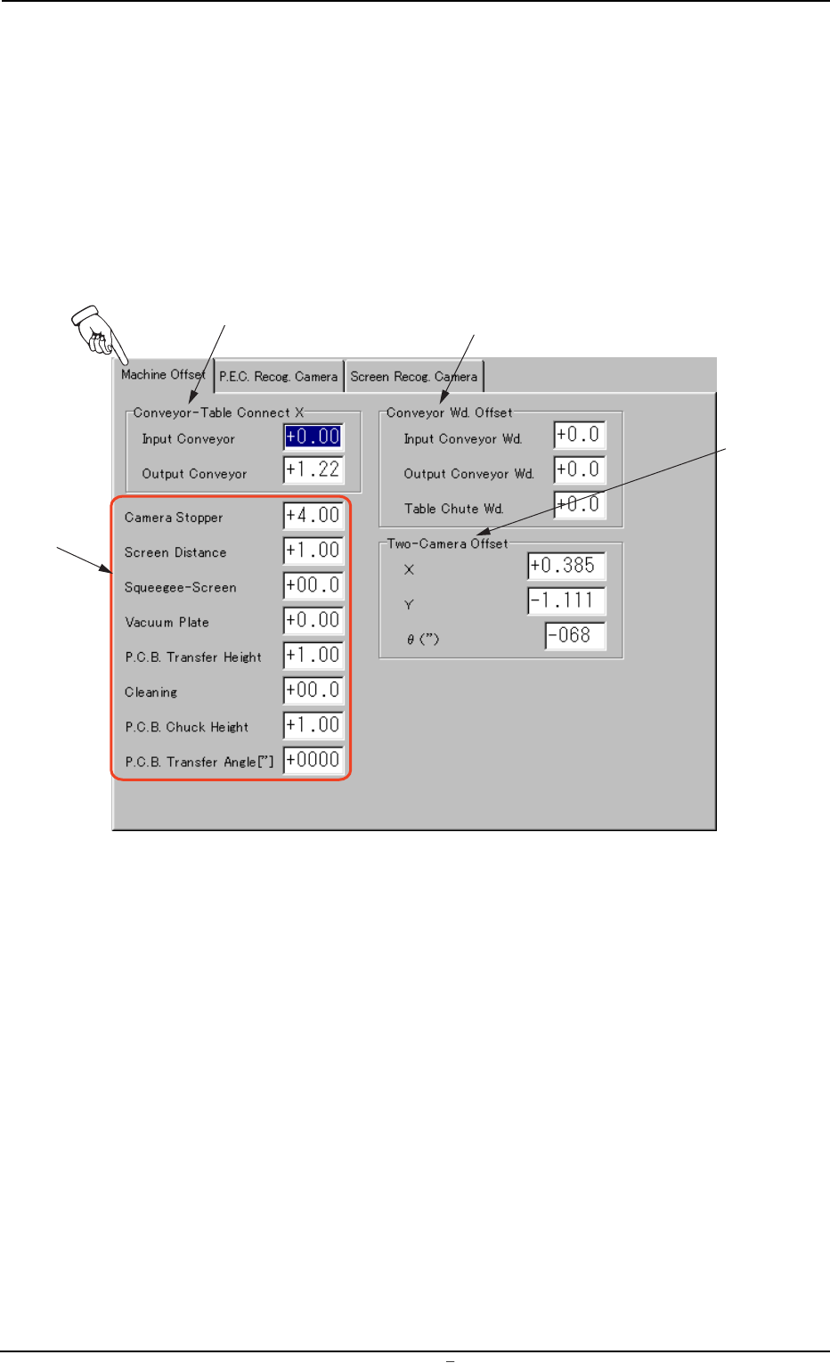
4.1 "Machine Offset" Tab
This tab sheet enables the operator to set offset values for each section
of the machine.
• Sheet Layout
When "Machine Offset" tab is pressed at the "OFFSET DATA" window
(submenu), the following tab sheet appears.
Fig. 3D13 "Machine Offset" Tab Sheet
• Sheet Layout
*1 Conveyor-Table Connect X (Horizontal)
Enter clearances (dimensions) in the X direction of the terminal
areas between the L/R conveyors and the table chute. The en-
tered values are used to change the specified ones.
*3
*1
*2
*4
0106-003 Chapter 1 4 20 AFU01EDTP
4.1
"
Machine Offset
"
Tab
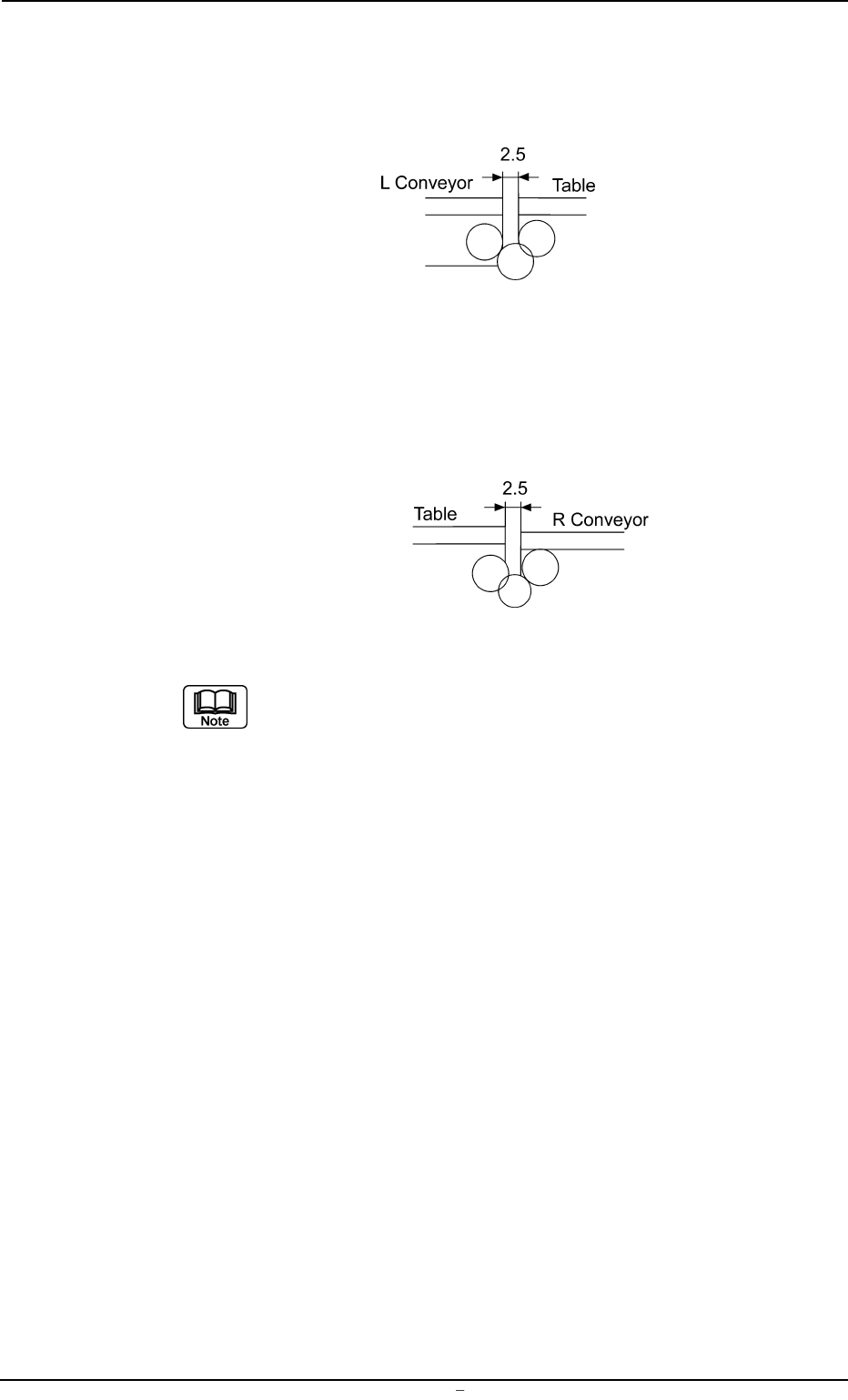
Input Conveyor : Enter an offset value based on the specified
one (2.0 mm) as a clearance (dimension) in
the X direction of the terminal area between
the L conveyor and the table chute.
Fig. 3D13-1
Output Conveyor : Enter an offset value based on the specified
one (2.0 mm) as a clearance (dimension) in
the X direction of the terminal area between
the R conveyor and the table chute.
Fig. 3D13-2
Make the ten-key window appear and enter the offset val-
ues in the text boxes.
*2 Conveyor Wd. Offset
Enter dimensions (widths) in the Y direction of the L/R conveyors
and the table chute through which a P.C.B. passes. The entered
values are used to change the specified ones in the pattern pro-
gram.
Input Conveyor Wd. : Enter an offset value (the dimension
representing the width through which
a P.C.B. on the L conveyor passes)
based on the specified one in the pat-
tern program.
Output Conveyor Wd. : Enter an offset value (the dimension
representing the width through which
a P.C.B. on the R conveyor passes)
based on the specified one in the pat-
tern program.
Table Chute Wd. : Enter an offset value (the dimension
representing the width through which
a P.C.B. on the table chute passes)
based on the specified one in the pat-
tern program.
0009-002 Chapter 1 4 21 AFU01EDTP
4.1
"
Machine Offset
"
Tab
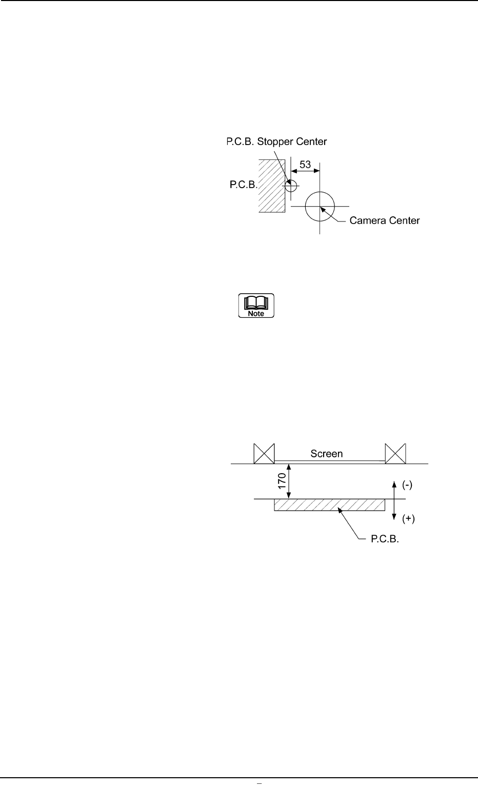
*3 Offset Entry Area for Each Unit
Offset values can be entered for each unit.
Camera Stopper : When the P.C.B. stop position has de-
viated from the table center, set the
offset data for the correction.
Fig. 3D13-3
The offset can automatically be
set through the teaching op-
eration.
Screen Distance : Enter an offset value in the text box,
based on the specified distance in the
Z direction between the underside of
the screen and the upper surface of the
P.C.B. for printing.
Fig. 3D13-4
0106-003 Chapter 1 4 22 AFU01EDTP
4.1
"
Machine Offset
"
Tab