2OM-1104-001.pdf - 第349页
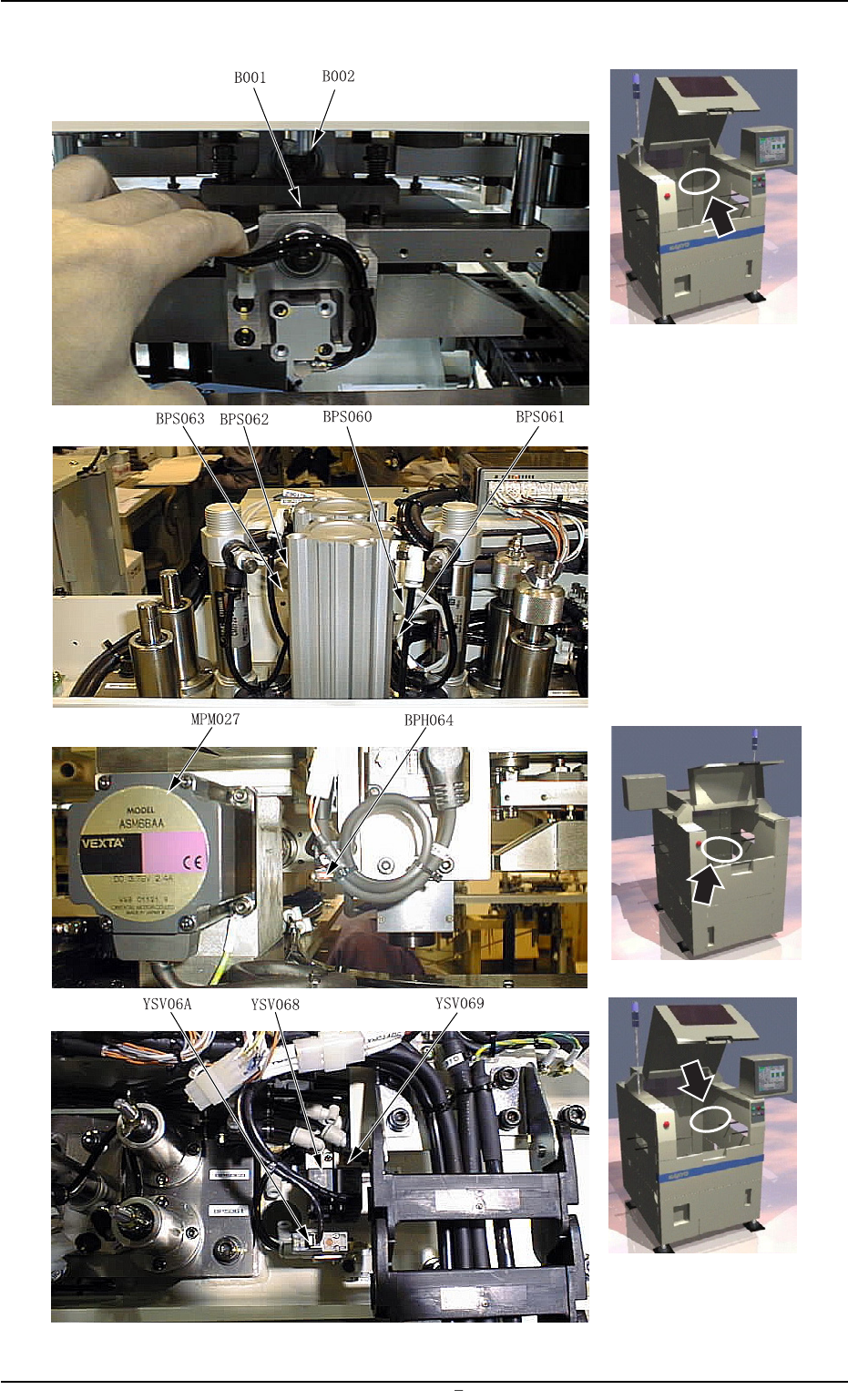
0106-002 Chapter 3 3 54 AFU01EDTP Fig. 5C10 T able 5C6 Symbols Name B001 Front Load Cell B002 Rear Load Cell BPS060 Front Squeegee U/D Upper Limit BPS061 Front Squeegee U/D Middle BPS062 Rear Squeegee U/D Upper Limit BPS…
0106-002 Chapter 3 3 53 AFU01EMTP
3.5 Location of Sensors in Squeegee Section
3.5 Location of Sensors in Squeegee Section
Fig. 5C9
0106-002 Chapter 3 3 54 AFU01EDTP
Fig. 5C10
Table 5C6
Symbols Name
B001 Front Load Cell
B002 Rear Load Cell
BPS060 Front Squeegee U/D Upper Limit
BPS061 Front Squeegee U/D Middle
BPS062 Rear Squeegee U/D Upper Limit
BPS063 Rear Squeegee U/D Middle
BPH064 Paste Height Detection (Option)
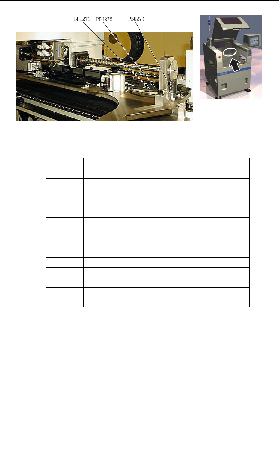
BPH271 Squeegee Driving Axis Origin
BPH272 Squeegee Driving Axis Limit
BPH274 Squeegee Driving Axis Rotational Origin
MPM027 Squeegee Driving Axis Pulse Motor
YSV068 Front Squeegee U/D Solenoid Valve
YSV069 Rear Squeegee U/D Solenoid Valve
YSV06A Squeegee Middle Stopper (Outward)
3.5 Location of Sensors in Squeegee Section
0106-002 Chapter 3 3 55 AFU01EDTP
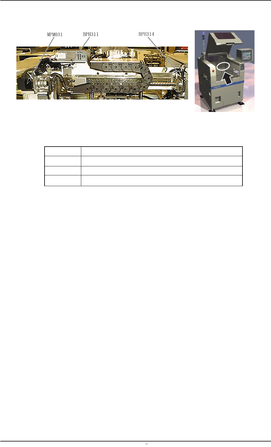
3.6 Location of Sensor in Screen Recognition Section
3.6 Location of Sensor in Screen Recognition Section
Fig. 5C11
Table 5C7
Symbols Name
BPH311 Screen Recognition X-Axis Origin
BPH314 Screen Recognition X-Axis Rotational Origin
MPM031 Screen Recognition X-Axis Pulse Motor