2OM-1104-001.pdf - 第271页
(a) When the rubber squeegees are worn out, the push- ing distance becomes as short as they are worn out. Therefore, it is required to change the rubber squee- gees before the pushing distance is changed greatly (in the …
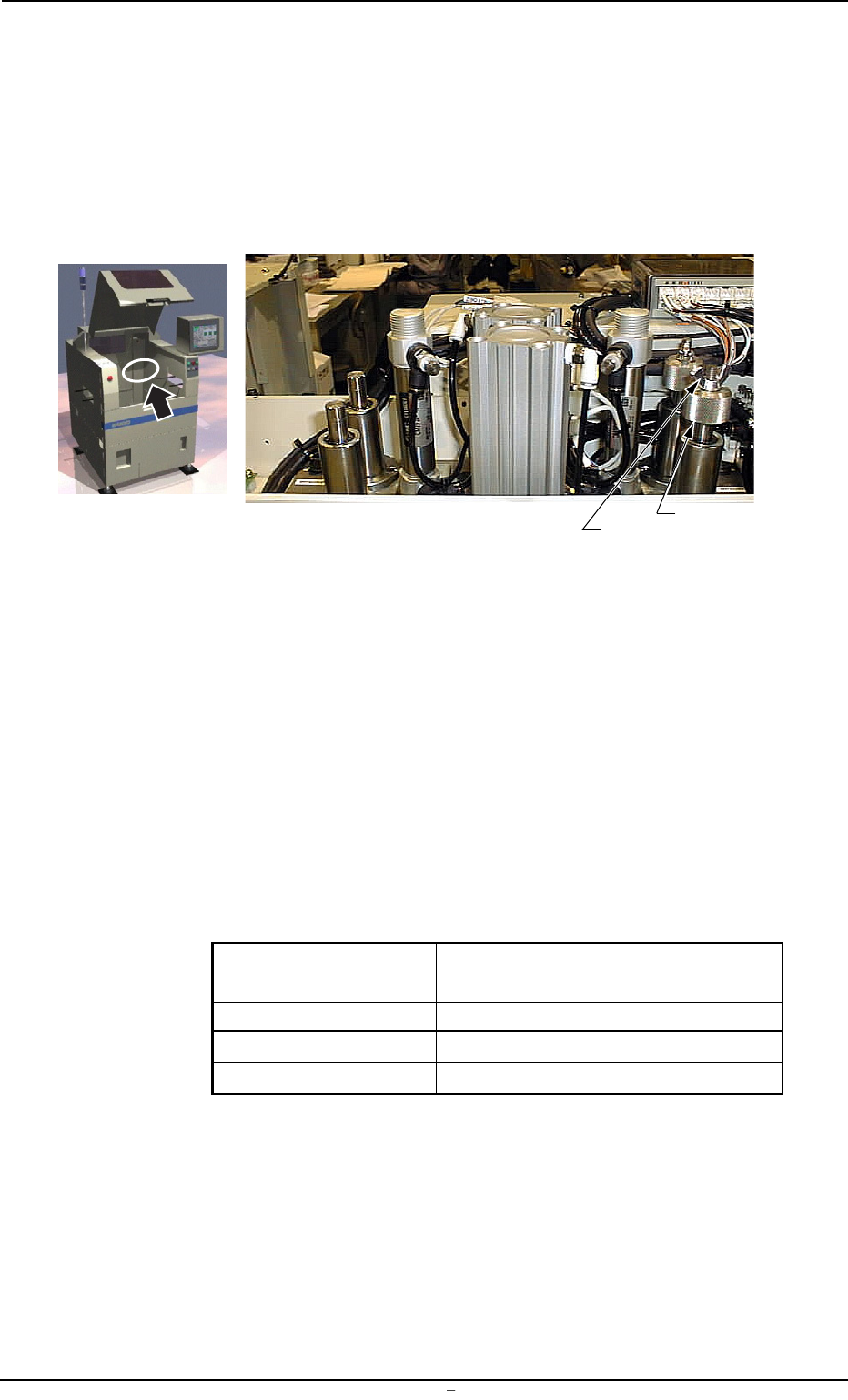
9.1.1 Adjustment of Squeegee Head Height
••
••
• Rubber Squeegees
Adjustment Procedure
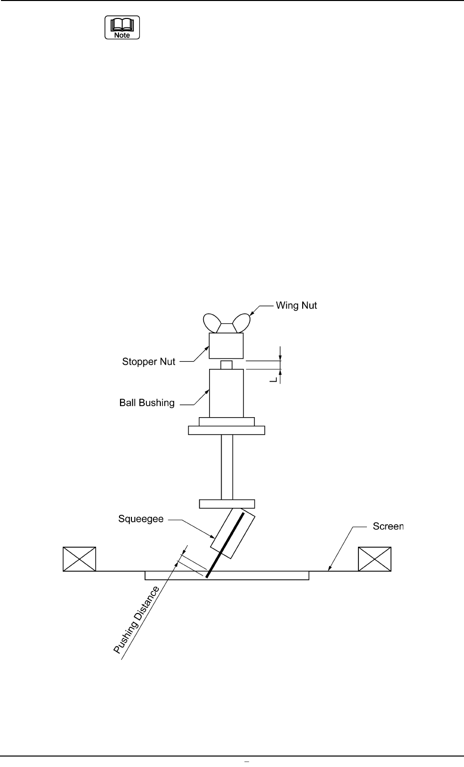
(1) Loosen the wing and stopper nuts.
Fig. 5A37-1
(2) Adjust the pushing distance by changing Dimension L (the dis-
tance between the upper end plane of the ball bushing and the
lower end plane of the stopper nut).
The pushing distance of the squeegee against the screen is set
to “1.0 mm”. (Factory-Adjusted upon Shipment)
When the stopper nut is turned once clockwise, the pushing
distance becomes shorter by 1.0 mm.
Turning the stopper nut once counterclockwise makes the push-
ing distance longer by 1.0 mm.
Ref.:
Pushing Distances Dimension L during Upward
Movement of Cylinder
0.5 mm 58.5 mm
1.0 mm 59.0 mm (Standard Setting)
1.5 mm 59.5 mm
(3) Open the “SEMI-AUTO OPN.” window (submenu) or the “Print
Block” tab sheet of the “MAN. SUB-SYS” window (submenu)
and push the squeegee against the P.C.B. located in the print-
ing section.
Refer to the above table and check the relation between Di-
mension L and the pushing distances.
Wing Nut
Stopper Nut
0106-002 Chapter 3 1 31-1 AFU01EINP
9.1 Replacement of Squeegees
(a) When the rubber squeegees are worn out, the push-
ing distance becomes as short as they are worn out.
Therefore, it is required to change the rubber squee-
gees before the pushing distance is changed greatly
(in the range of 0.5 mm or less).
(b) The rubber squeegees can be ground to be re-used.
In this case, the total of the dimension (grinding) is
limited to “1.5 mm” (when the maximum pushing dis-
tance is “0.5 mm”).
When the total of the dimension (grinding) has be-
come “1.5 mm”, be sure to replace the rubber squee-
gees with new ones.
(c) When the rubber squeegees are ground to be re-used,
lower the location of the stopper nuts according to
the dimensions of the ground rubber squeegees (the
squeegees that have become shorter after grinding)
so that the same pushing distances can be kept.
Fig. 5A37-2 Conceptualized Pushing Distance
0106-002 Chapter 3 1 31-2 AFU01EINP
9.1 Replacement of Squeegees
• Metal Squeegees with Holders (Incorporated with Holders)
Example : Permalex: PLX-A3060-270, PLX-A3060-350
When the metal squeegees are attached with the same
settings as the rubber squeegees, the clearances be-
tween the squeegees and the screen are changed in
the height direction because the blades are located at
the center of the holder thickness, making the push-
ing distances insufficient. Therefore, it is required to
adjust the pushing distances.
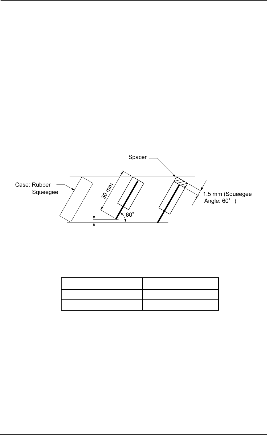
Adjustment Procedure for Spacer Use
(1) When spacers (thickness: 1.5 mm) are inserted as shown be-
low before the metal squeegees are attached to the squeegee
holders, the pushing distances can be kept to “1.0 mm” (same
as the rubber squeegees). (Squeegee Angle: 60°, Squeegee
Height: 30 mm)
Fig. 5A37-3
Refer to the table below before purchasing spacers.
Spacer Length Part No.
270 mm 630 097 6656
350 mm 630 097 6663
0106-001 Chapter 3 1 31-3 AFU01EINP
9.1 Replacement of Squeegees