2OM-1104-001.pdf - 第161页
2.1 T ypical Description T able 4B4 Error ID Item Description 1 10401 L Conveyor Width Overrun The plus (+) overrun was detected. (BPH77) E/NR (+) E/NR: Light Emitted and Not Received 1 10402 L Conveyor Width Overrun The…
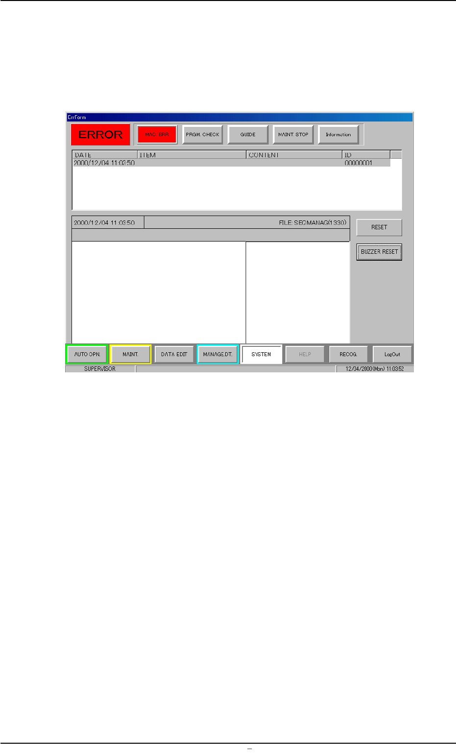
2. Troubleshooting after Error Display
Assuming "ID/ITEM/CONTENT" in the "ERROR" window as an index,
retrieve the related page of the instruction manual.
Refer to "2.1 Typical Description" for the detailed description.
Fig. 4B3 Example of "ERROR" Window
2. Troubleshooting after Error Display
0009-001 Chapter 2 2 5 AFU01ETRP
2.1 Typical Description
Table 4B4
Error ID Item Description
110401 L Conveyor Width Overrun The plus (+) overrun was detected.
(BPH77) E/NR (+)
E/NR: Light Emitted and Not Received
110402 L Conveyor Width Overrun The minus (-) overrun was detected.
(BPH77) E/NR (-)
(Cause 1) An optical beam of the sensor is shielded.
(Cause 2) Dirt adheres to the sensor and the optical beam is shielded.
(Cause 3) The sensor is defective.
(Remedy 1) Turn off the power supply and move the conveyor width with the manual
knob for easier operation. Re-attach the light shield plate or the sensor
securely (remove the looseness).
(Remedy 2) Wipe off dirt on the sensor and zero the L conveyor again.
(Remedy 3) Replace the sensor with a new one.
120101 R Conveyor Width Origin The excitation monitor signal was not de-
tected.
(Cause 1)
(Remedy 1)
(Continued to the next page)
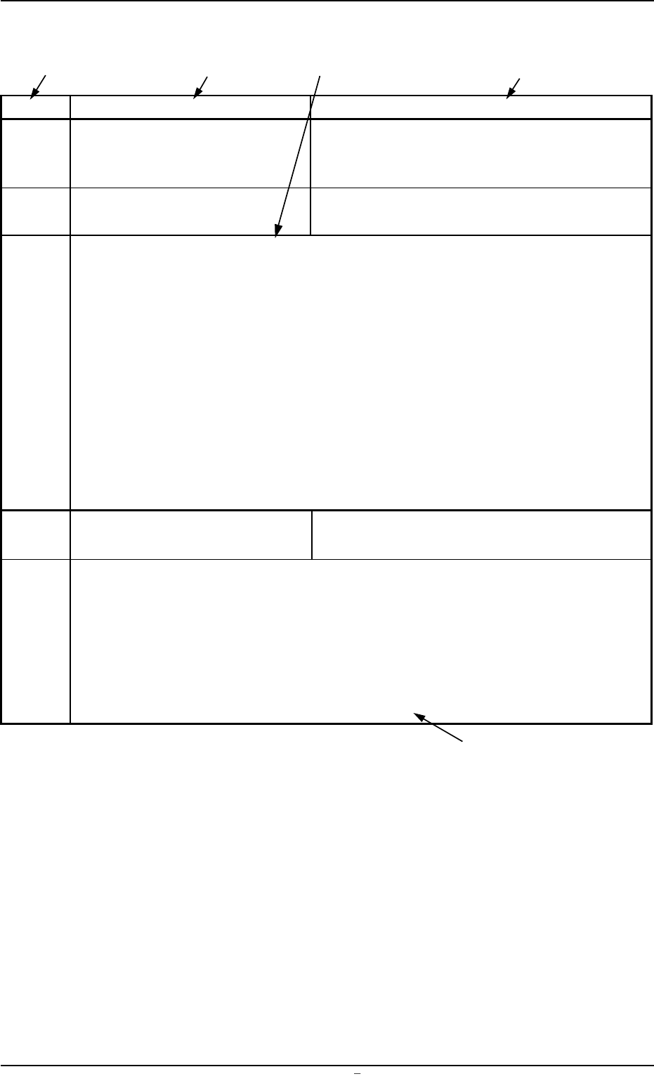
*1 The error IDs (IDs displayed in the "ERROR" window) are described
in the numerical order.
*2 Described are the classification (ITEM) and explanation (CONTENT)
in the "ERROR" window.
*3 Described are the causes and remedial procedures of the errors in
"*2 (Classification and Explanation)".
The causes and remedies are correlated as follows.
(Cause 1)
ÆÆ
ÆÆ
Æ (Remedy 1)
(Cause 2)
ÆÆ
ÆÆ
Æ (Remedy 2)
(Cause 3)
ÆÆ
ÆÆ
Æ (Remedy 3)
*4 This indicates that the related contents are described subsequently
on the next page.
2.1 Typical Description
0009-001 Chapter 2 2 6 AFU01ETRP
*2
*3
*1
*2
*4
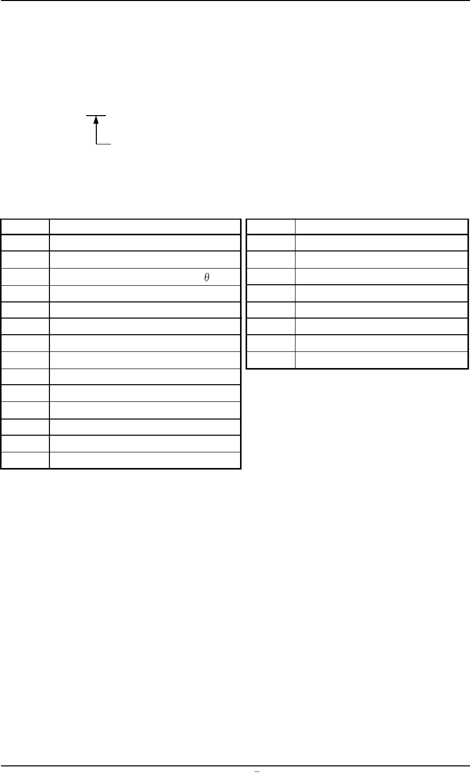
2.2 Error IDs and Controlled Areas
Basic System of Error IDs
An error ID is expressed by 7 digits (decimal number) as follows.
Major Classification of "Operating Axis", "Process Error", and
"Teaching Operation"
Error IDs and Controlled Areas
Table 4B5
Error ID Operating Axis Error ID Process Error
01 Table-X Axis 15 Safety Device
02 Table-Z Axis 16 Self-Diagnostics
03 Placement Z Correction Table
Axis 17 Material Shortage
04 Screen Y Axis 18 P.C.B. Recognition
05 Squeegee Driving Axis 19 Screen Recognition
06 P.E.C. Recognition Camera X Axis 20 Cleaning
07 P.E.C. Recognition Camera Y Axis 21 Operator’s Error
08 Screen Recognition Camera X Axis 22 Others
09 P.C.B. Backup Axis
10 Table Chute Width
11 Input Conveyor
12 Output Conveyor
13 P.C.B. Transfer
14 Squeegee Head
2.2 Error IDs and Controlled Areas
0009-001 Chapter 2 2 7 AFU01ETRP