CAN Bus Workshop_Version 03__06-2008_EN.pdf - 第102页
1 Caccia Student Guide CACCIA Manual Issue 04/2007 EN 10 Machines types: 1 1 Placement head types : 1 1 Others: 1 1 F5HM 1 gantry machine with DLM2 C&P6 or DLM2 C&P12 heads and IC head X-2 2 gantry machine with a…
CACCIA Manual 1 Caccia Student Guide
Issue 04/2007 EN
9
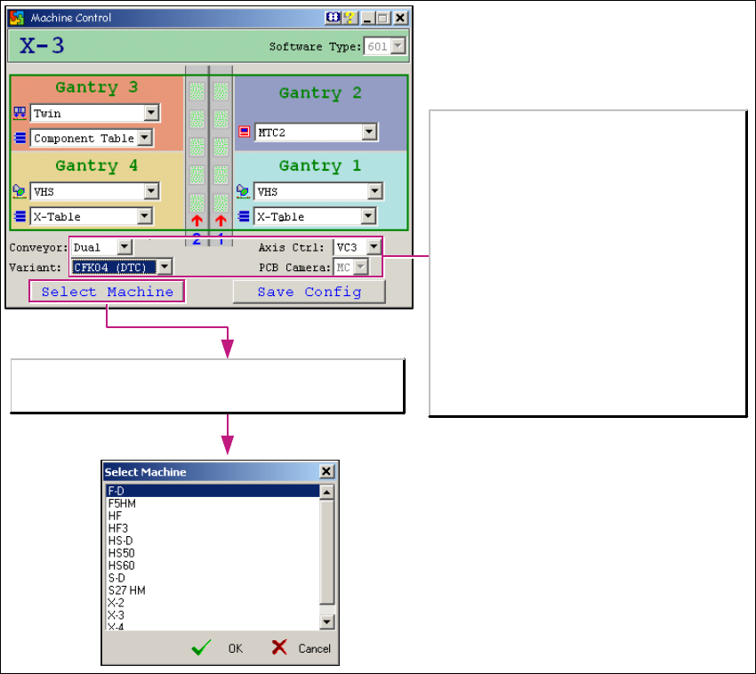
→ The Select Machine button opens the Select Machine dialog box:
1
Fig. 1 - 5 "Select machine" dialog box
You can select the required machine here. 1
1
The Select Machine button opens the Select Machine
dialog box.
Variant (gantries):
HF series:
-CFK02
-CFK04
X series:
-CFK04
-CFK06
Axis Control:
- VC3 with A363
-A364
PCB Camera:
- MC (Multi Color), option
- SSt34 (Camer light) for X and D series
- UP, MC for HF series

1 Caccia Student Guide CACCIA Manual
Issue 04/2007 EN
10
Machines types:
1
1
Placement head types:
1
1
Others:
1
1
F5HM
1 gantry machine with DLM2 C&P6 or DLM2 C&P12
heads and IC head
X-2
2 gantry machine with all 4 head types possible on all
gantries
X-3
3 gantry machine with C&P heads on G1/G4 and C&P6/
1220 or Twin on G3
X-4
4 gantry machine with C&P heads on all gantries -same
types required in any one placement area
HF HF series
HF3 HF series
HS50(VC2)
HS60(VC2)
HS machines in their current series versions
D1 D series
D1+ D series
D2 D series
D3 D series
D4 D series
S27HM
2 gantry machine with DLM2 C&P6 and/or DLM2 C&P12
heads
DLM2 RV 6 C&P 6 placement head during the development phase
DLM2 RV 12 C&P 12 placement head during the development phase
DLM2 16Bit RV
6
C&P 6 placement head series with 16 Bit CAN processor on head
interface
DLM2 16Bit RV
12
C&P 12 placement head series with 16 Bit CAN processor on head
interface
VHS head C&P 20 placement head
Component
table
CO table for S feeder
X-Table CO table for X feeder
MTC2 MTC 2 for location 2 of X3 and X2 at location 4
CACCIA Manual 1 Caccia Student Guide
Issue 04/2007 EN
11
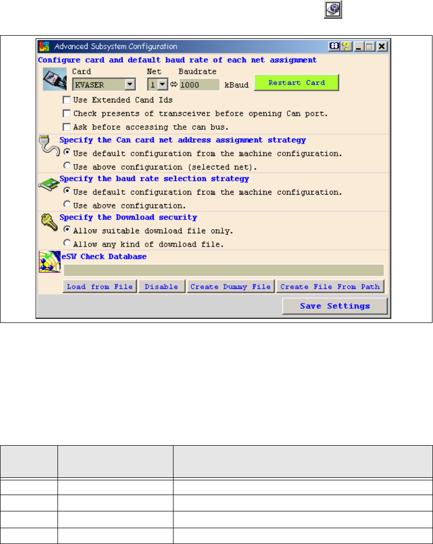
1.1.4 Change Properties - Advanced Subsystem Configuration
→ Open the Advanced Subsystem Configuration dialog box with the button:
1
Fig. 1 - 6 Advanced subsystem configuration dialog box
CAN card configuration and default baud rate setting: 1
–CAN card:
Select the CAN card which is installed on the system concerned. 1
– Net, baud:
1
1
– Restart card
Restarts the selected CAN card. 1
Net
Baud
1 Kbaud = 1 Kbit/s
Machine(s)
1, 2 1000 Kbaud For X2/X3/X4 and HF/HF3 machines.
1 500 Kbaud For HS 50/ HS 60 machines
2 125 Kbaud For HS 50/ HS 60 machines
1 1000 Kbaud S27HM