CAN Bus Workshop_Version 03__06-2008_EN.pdf - 第170页
1 Caccia Student Guide CACCIA Manual Issue 04/2007 EN 78 Fig. 1 - 52 1 Wire CA T 5 Splitter (03040219-01) Fig. 1 - 53 1 Wire trailing interface board (03042214-01) 2 Input CA T 5 cable from RS 232 Interface Input 24 V fo…
CACCIA Manual 1 Caccia Student Guide
Issue 04/2007 EN
77
One wire bus components 1
Assemblies:
1. 1 wire RS232 bridge on the SUB/MAIN module (to be later integrated into the I/O module)
2. 1 wire CAT 5 Gantry on the trailing interface (board between CAN bus and trailing interface)
3. 1 wire CAT 5 Splitter
4. 1 wire hub for nozzle changer
5. Control board for nozzle changer (integrated into NC, not for DLM heads)
6. 1 set of temperature sensors (replacement only as a set, due to serial number)
7. EEPROM for gantry recognition
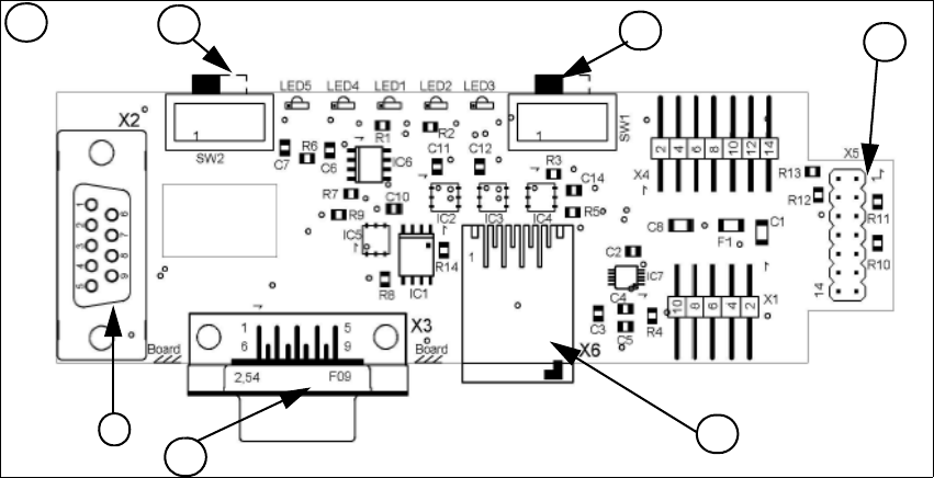
Fig. 1 - 51 1 Wire RS232 interface (03041578-01)
(1) CAN Bus Interface to I/O module (2) RS 232 Interface
(3) CAN Bus interface to the machine (4) Switch to recognize the version of the I/O mo-
dule Version 02/03
(5) Switch MA / PC switch to MA (machine) (6) Connector CAT5 cable
LED 1 nozzle changer gantry 1/3 LED 2 Temperatur sensor
LED 3 nozzle changer gantry 4/2 LED 4 Green "OK"
LED 5 Green "Fail"
4
1
2
3
1
5
6
1 Caccia Student Guide CACCIA Manual
Issue 04/2007 EN
78
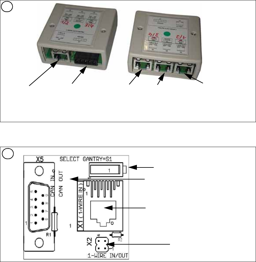
Fig. 1 - 52 1 Wire CAT 5 Splitter (03040219-01)
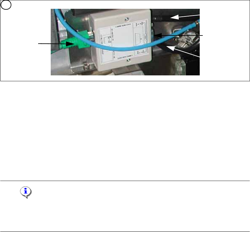
Fig. 1 - 53 1 Wire trailing interface board (03042214-01)
2
Input CAT 5 cable
from RS 232 Interface
Input 24 V for
NC
Output CAT 5
to the NC HUB
Gantry 3or 4
Output CAT 5 to
the 1 Wire gan-
try board
Output CAT 5
to the NC HUB
Gantry 1or 2
3
Switch: position below Gantry 1/2
position above Gantry 3/4
This board is located directly on the CAN
bus connector of the trailing interface.
Connector CAT5 cable from the 1 wire
distributor
Connection to the second Gantry in the
placement area
CACCIA Manual 1 Caccia Student Guide
Issue 04/2007 EN
79
Fig. 1 - 54 1 wire hub for NC (03041473-02)
Note
In future we don‘t have the switch for the location code (only HF). The location code for the noz-
zlechanger will be realized via hardware, directly in the connector on the location (X112 / X122 /
X132 / X142) at HF and Siplace X. 1
(1) Input CAT 5 cable from the CAT 5
splitter
(2) SUB-D connector for option (query reject con-
tainer)
(3) Connection NC 1 (4) Connection NC 2
on the right side display (2 LED‘s) for NC C&P6/12 Light barrier NC open/closed and Valve NC
open/closed for each row
on the left side two LED‘s directly on the connector
yellow LED: Reject box components connected
green LED: Reject box nozzles connected
4
1
2
3
4