CAN Bus Workshop_Version 03__06-2008_EN.pdf - 第168页
1 Caccia Student Guide CACCIA Manual Issue 04/2007 EN 76 Depending on the mac hine configur ation (1 or 2 ga nt ries) the one wire bus structure in P A2 is iden- tical with that in P A1. Function description: 1 When the …
CACCIA Manual 1 Caccia Student Guide
Issue 04/2007 EN
75
Depending on the machine configuration (1 or 2 gantries) the one wire bus structure in PA2 is iden-
tical with that in PA1.
1.11.1.3 One Wire Bus in the Siplace X
With the Siplace X-machine the One Wire Bus is integreted in a separate CAT5 cabel, which start
from the Main- and Subdistributor up to the trailling interface. From the trailing interface up to the
head interface the one wire bus goes through the trailling cable. So that the cable structur are dif-
ferent but not the function of the one wire bus. 1
1
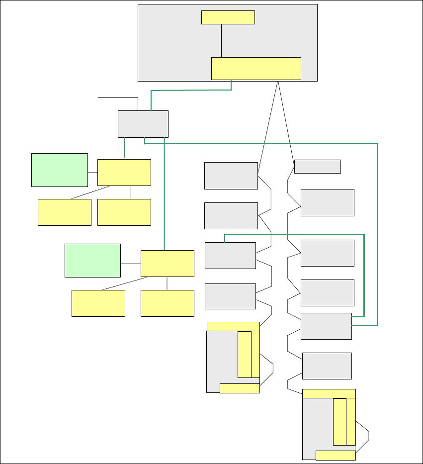
Fig. 1 - 49 Overview of one wire subsystems e.g. PA1 on the Siplace X
Vision control
unit
Sector 4
Transport
Control unit
Axis unit
PA 1
COM Board
I/O SUB Module
Sector 4
One Wire Bridge
(driver)
Nozzle changer
Hub (Coupler)
Gantry 4
CO-Table 4
Tape cutter
Conrol board
NC (C&P20)
row 1
Control board
NC (C&P20)
row 2
Trailing -Interface
Gantry 4
CO-Table 1
Tape cutter
Trailing-Interface
Gantry 1
Temp.sensor
Head
plate
Temp.sensor
Option: Check reject bin
or terminating plug
Attention: no CAN-
termination resistor
TQM Module
(Master)
RS232
Machine CAN Bus
1 Wire CAT5
Gantry 4
Headinterface
1 Wire CAT5
Gantry 4
Temp.sensor
Head
plate
Temp.sensor
Gantry
recognition
Headinterface
1 Wire CAT5
Distributor
24V for the nozzle changer
1 Wire CAT5 cable
1 Wire CAT5 cable
1 Wire CAT5 cable
1 Wire CAT5 cable
1 Wire CAT5 cable
Nozzle changer
Hub (Coupler)
Gantry 1
Control board
NC (C&P20)
row 2
Conrol board
NC (C&P20)
row 1
Option: Check reject bin
or terminating plug
Attention: no CAN-
termination resistor
Gantry
recognition
1 Caccia Student Guide CACCIA Manual
Issue 04/2007 EN
76
Depending on the machine configuration (1 or 2 gantries) the one wire bus structure in PA2 is iden-
tical with that in PA1.
Function description: 1
When the machine is switched on, each one wire bus is assigned a fixed CAN ID.
One wire in PA1 --> CAN ID: 07d0
One wire in PA2 --> CAN ID:07c0
During initialization of the bus system, each station registers with the master, after which the bus
is ready for operation.
In the non operative mode, the voltage level is 5 V on the one wire bus.
A repeat initialization can be performed with the CACCIA tool (see Function Control and Trouble-
shooting for Service Work).
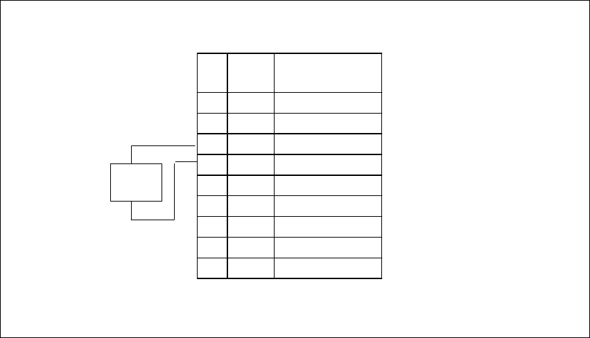
Pin assignment in machine CAN bus:
Fig. 1 - 50 Pin assignment for sub D connectors
120
Ohm
CAN Interrupt95
+24V 1-wire-Bus89
Power Fail74
CAN Reset68
GND53
CAN High47
CAN Low32
GND26
1-wire-Bus 11
AderPin
Pin 1 only for HF machines
CACCIA Manual 1 Caccia Student Guide
Issue 04/2007 EN
77
One wire bus components 1
Assemblies:
1. 1 wire RS232 bridge on the SUB/MAIN module (to be later integrated into the I/O module)
2. 1 wire CAT 5 Gantry on the trailing interface (board between CAN bus and trailing interface)
3. 1 wire CAT 5 Splitter
4. 1 wire hub for nozzle changer
5. Control board for nozzle changer (integrated into NC, not for DLM heads)
6. 1 set of temperature sensors (replacement only as a set, due to serial number)
7. EEPROM for gantry recognition
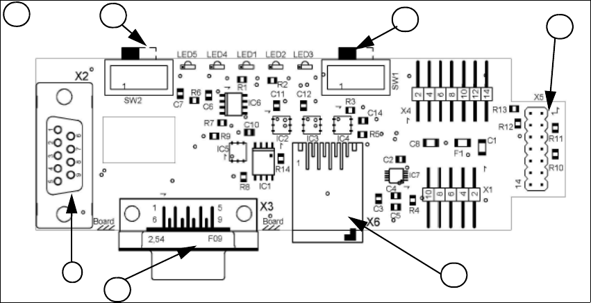
Fig. 1 - 51 1 Wire RS232 interface (03041578-01)
(1) CAN Bus Interface to I/O module (2) RS 232 Interface
(3) CAN Bus interface to the machine (4) Switch to recognize the version of the I/O mo-
dule Version 02/03
(5) Switch MA / PC switch to MA (machine) (6) Connector CAT5 cable
LED 1 nozzle changer gantry 1/3 LED 2 Temperatur sensor
LED 3 nozzle changer gantry 4/2 LED 4 Green "OK"
LED 5 Green "Fail"
4
1
2
3
1
5
6