CAN Bus Workshop_Version 03__06-2008_EN.pdf - 第47页
1 - 21 S tudent Guide CAN BUS W orkshop Edition 0 6 /2008 2 Comm unication and Control 21 2.2.8 CAN I/O Module (SLIO) Siplace X SIPLACE X ma chine s use 2 CAN I/O mod ules. Both module s are a bsol utely id entical and a…
1 - 20
Student Guide CAN BUS Workshop
2 Communication and Control Edition 06/2008
20
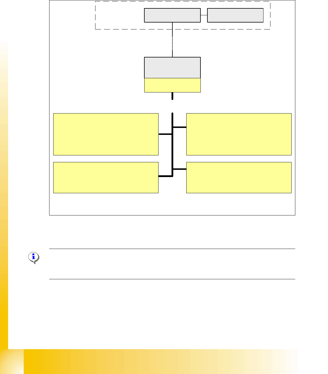
2.2.7.3 CAN Bus controlled function on the Twin Head
The CAN-Bus Processor-board is no longer on each Twin segment installed. Now, the Twin seg-
ment got a new board and the processor board (TQM) is installed on the head board C500. The
reason is, that we have a defined interface for head modularity.
Fig. 2.2 - 18 Function on the Can Bus Processor Twin Head
NOTE:
The status of the 16 bit PROCESSOR BOARD is indicated on the 7-segment display.
Normal status on the diplay is: " . " flashed
Vacuum/Air kiss generator Segment 1
1. Adjust vacuum/air kiss
2. Measurement vacuum/air kiss
3. Reject function
Computer Unit
COM Board
Machine- CAN Bus
(1MBit/s)
Control of the following functions
MC
Head processor
C500
TQM-module
Force measurement board Segment 1
1. Activation
Function control force measurement
directly on the axis controller A363
Vacuum/Air kiss generator Segment 2
1. Adjust vacuum/air kiss
2. Measurement vacuum/air kiss
3. Reject function
Force measurement board Segment 2
1. Activation
Function control force measurement
directly on the axis controller A363
1 - 21
Student Guide CAN BUS Workshop
Edition 06/2008 2 Communication and Control
21
2.2.8 CAN I/O Module (SLIO) Siplace X
SIPLACE X machines use 2 CAN I/O modules. Both modules are absolutely identical and are lo-
cated in sectors 2 (main distributor) and 4 (subdistributor). The introduction of the one wire bus
system means that there is now an additional board plugged into the I/O module (Interface 1-Wire
CAT5 / Interface 1-Wire CAN 2 used for WPC-option with SW 605).
– Micro controller with integrated CAN controller
–Data memory
– Program memory (flash)
– CAN interface with 9 pin connector and address alignment
– 16 digital Output 24 V with status LED
– 24 digital Input 24 V with status LED
– Download interface
– Power supply 24V
The board on the I/O module "Interface 1-Wire CAT5" [03041578-xx] needs to be replaced with
the "Interface 1-Wire CAN2" [03065805-xx] board for the WPC option.
Attention: two different kind of CAN I/O modul 00355051-01/02 with an additional RS232 bridge
and 00355051-03 with integrated RS232 bridge for HF-machine. (TI 2005-08E03)
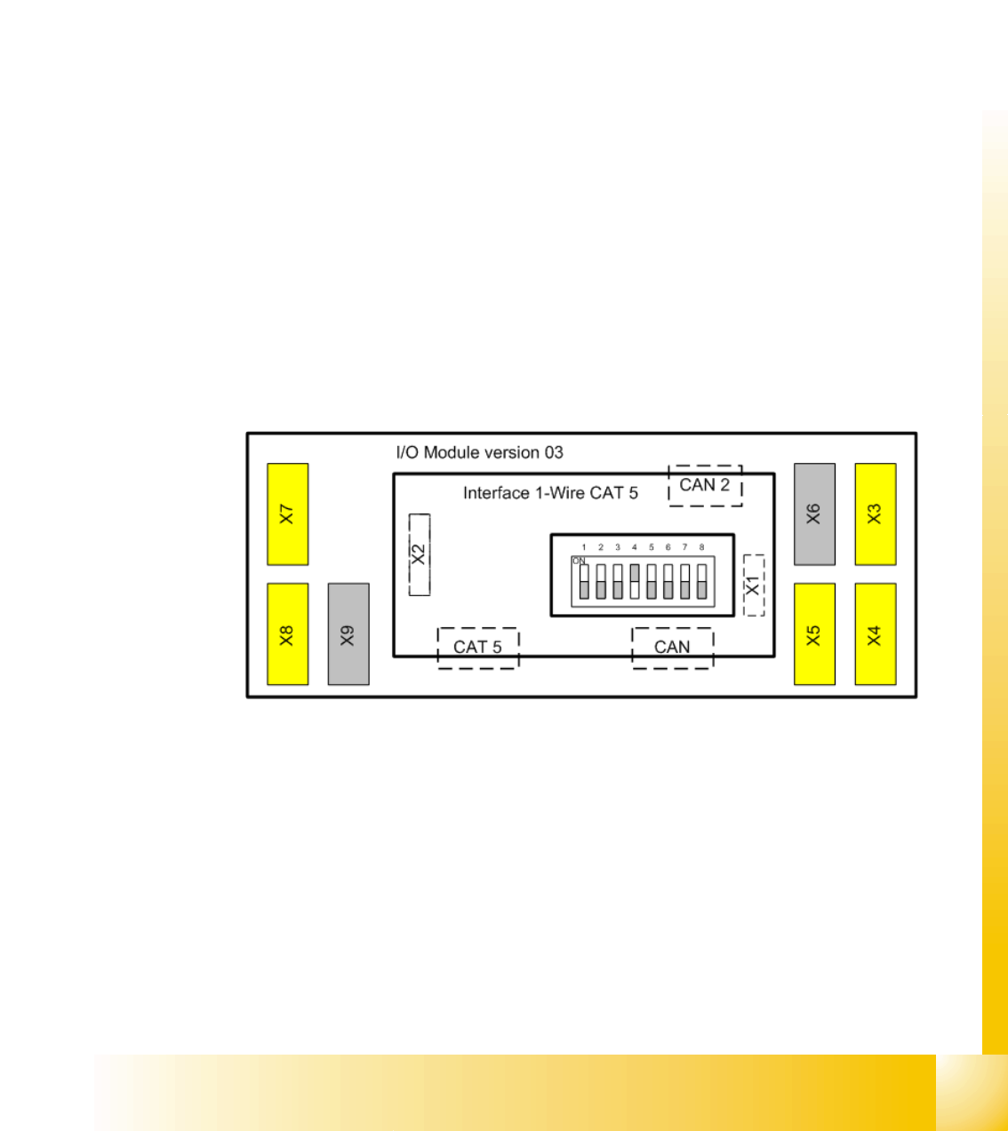
Fig. 2.2 - 19 Overview CAN I/O module
Legend
X1 CAN-Interface from the Interface to the
I/O module
X2 Connector for the RS232 Interface to supply
the ONE Wire
CAT 5: connecter for the one wire CAN connector for the machine CAN Bus
CAN 2 only available if you have the option WPC
X3, X4, X5 digital inputs 24V X6/X9 power supply 5V,24V,GND
X7, X8 digital outputs 24V DIP Switch is on the I/O module
1 - 22
Student Guide CAN BUS Workshop
2 Communication and Control Edition 06/2008
22
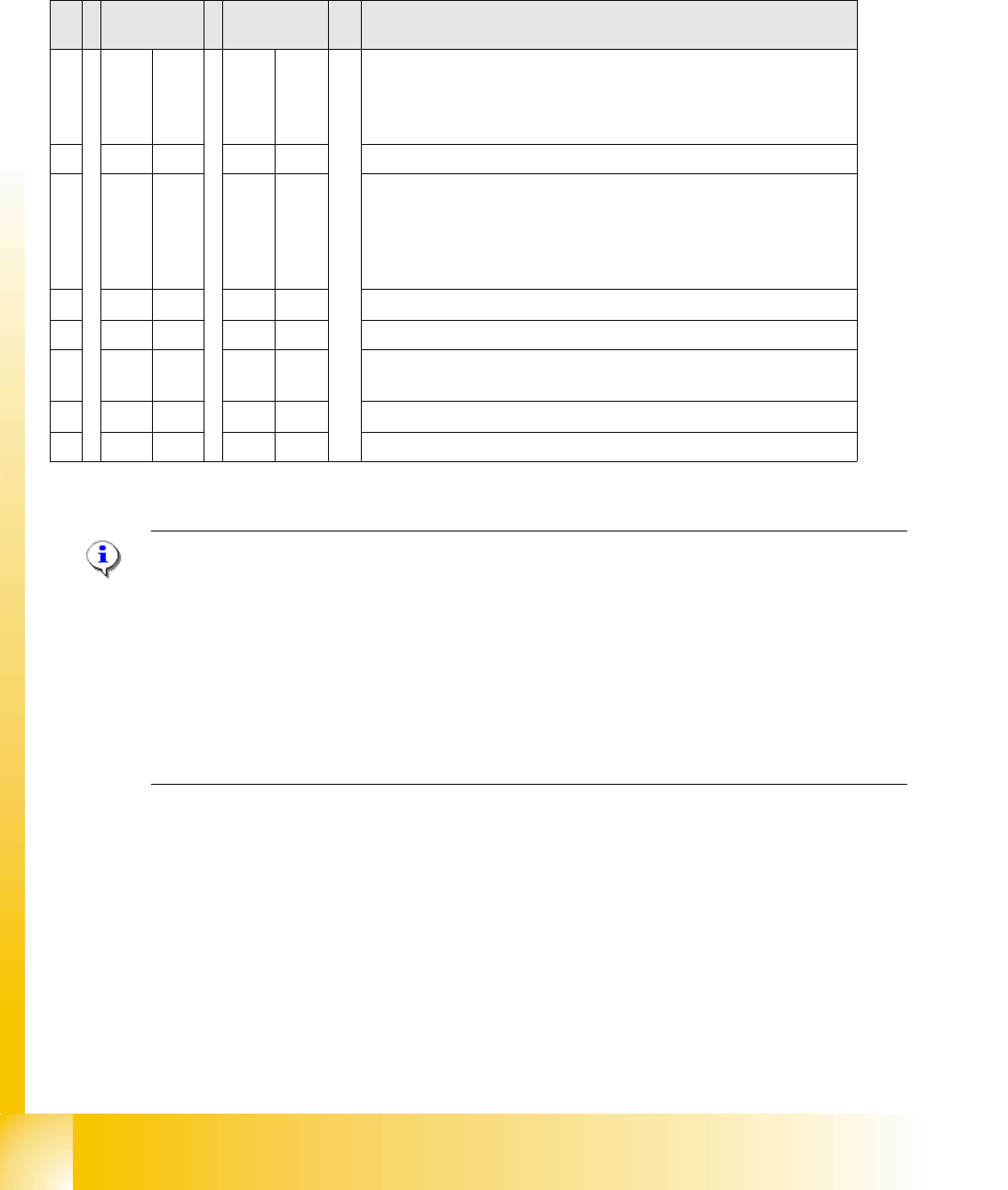
2.2.8.1 DIP Switch on Main and Subdistributor (for Version -03)
DIP switch on CAN I/O module (X-series from Ma No. B-326, X4I).
Applies for main distributors [03046225-xx] and subdistributors [03046226-xx].
NOTE:The I/O assemblies of version 02 and 03 differ in that the "Interface 1-Wire CAT5" board is
integrated into version 03. This means that this integrated "Interface 1-Wire CAT5" board can only
be used for HF/HF3 machines.
X machines have the "Interface 1-Wire CAT5" connected as an additional module, due to the
CAT5 connection. By setting the switch on the interface to
MA
and
Version 02
the integrated in-
terface is switched off and the machine uses the additionally connected interface.
The same I/O assembly is used for D series machines but with a different eSW. This results in
other DIP switch settings (see table above). The additionally connected interface is used to ad-
dress the components and cutters via a sub CAN bus.
S Main
distributor
Subdistribut
or
Comments
1OFF OFF Baud rate:
ON = 500 Kbit/s (for the D1, D2, D4 tables if the I/O module is used
for the D series),
OFF = 1 Mbit/s (X series X4I)
2OFF OFF SW platform: ON: HF/HF3, OFF: D3, X series X4I
3OFF OFF Baud rate:
ON: 500 KBit/s for D1/D2 machines, if switch S1 is ON.
ON: For X series (X2/X3) you need to enable the gateway for CAN2
and therefore the WPC4 option.
OFF (X4, X4I): There is no WPC4 installed.
4OFF ON Location: ON: Subdistributor, OFF: Main distributor
5OFF OFF Not in use
6OFF OFF OFF: The connected Interface 1-Wire CAT5 board is active if the
switches on it are set to V2 and MA.
7OFF OFF HW reset for 1-Wire
8OFF OFF OFF: X series, X4I, D4, ON: D1/D2