CAN Bus Workshop_Version 03__06-2008_EN.pdf - 第234页
1 - 26 Siplace C AN T est Box 1 CAN T est Box Edition 04/200 8 26 1.10.4 Overview of CAN Bus Structures for HF and HF/3 HF HF/3 Univ ersal cabl e har nes s Old ca ble ha rness COM KSP354 COM KSP 35 2 COM KSP 352 COM KSP …

1 - 25
Siplace CAN Test Box
Edition 04/2008 1 CAN Test Box
25
Comments:

1 - 26
Siplace CAN Test Box
1 CAN Test Box Edition 04/2008
26
1.10.4 Overview of CAN Bus Structures for HF and HF/3
HF
HF/3
Universal cable harnessOld cable harness
COM KSP354COM KSP 352
COM KSP 352 COM KSP354
SW 504 One
CAN bus per
machine
SW 505 One
CAN bus per
placement area
Version 01 Version 02
SW 504 One
CAN bus per
machine (was
not available)
SW 505 One
CAN bus per
placement area
COM KSP354COM KSP 352
SW 504 One
CAN bus per
machine
SW 505 One CAN
bus per placement
area (was not
available)
SW 505 One
CAN bus per
placement area
SW 504 One
CAN bus per
machine
Universal cable harnes
Version 02Version 01
Version 01 Version 02
1 - 27
Siplace CAN Test Box
Edition 04/2008 1 CAN Test Box
27
1.10.5 CAN Bus Structure for HF
1.10.5.1 General Differences
The HF machines will have the following differences:
– Communication assemblies 2x KSP 352 or one KSP 354
– HF machines with one CAN BUS for both placement areas are only supported by station soft-
ware versions 504.xx
– HF machines from station software version 505.xx only support the CAN bus structure with
one CAN bus per placement area.
– A difference is made between old and (new) universal cable harnesses.
This has the following consequences: 1
When checking or replacing the communication assemblies, always observe the terminating re-
sistors. Make sure you perform a physical check!
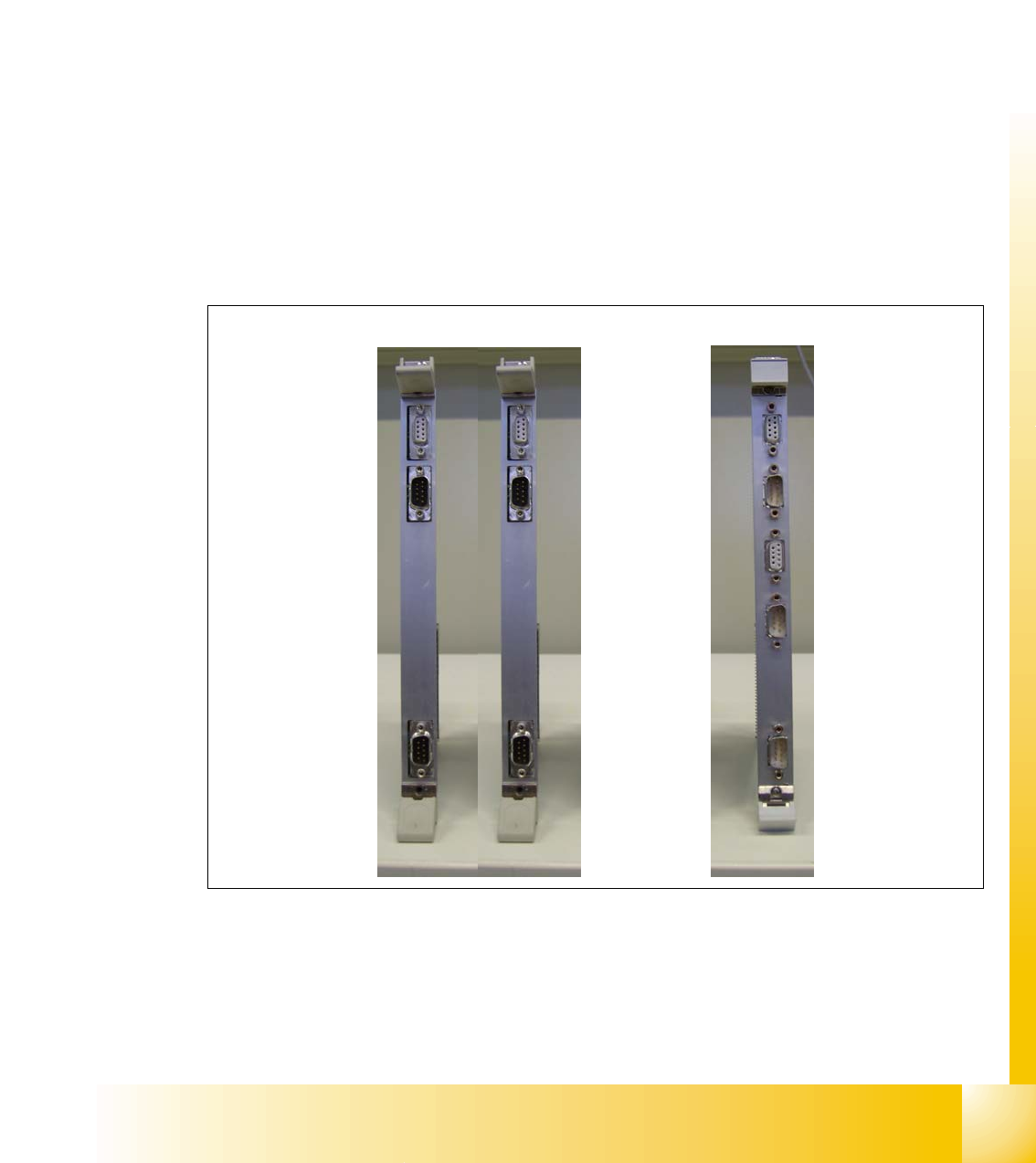
Fig. 1.10 - 6 KSP 352 and KSP 354 communication assemblies
COM KSP 354
COM KSP 352
X6
X7
X7
X6
X11
X12
X7
X6