CAN Bus Workshop_Version 03__06-2008_EN.pdf - 第71页
1 - 9 S tudent Guide CAN BUS W orkshop Edition 06/20 08 3 CAN B US 9 13 Dat um 06/ 2008 Vers io n 0 3 C AN Bu s W o rksh op M at hi a s Mic h el SIPL ACE Cam p us Aut om atio n and D rive s 3. P hysi kalische Überprüfung…
1 - 8
Student Guide CAN BUS Workshop
3 CAN BUS Edition 06/2008
8
11Dat um06/2008 Version 03 CAN Bus Workshop Mathias Michel
SIPLACE Campus
Automation and Drives
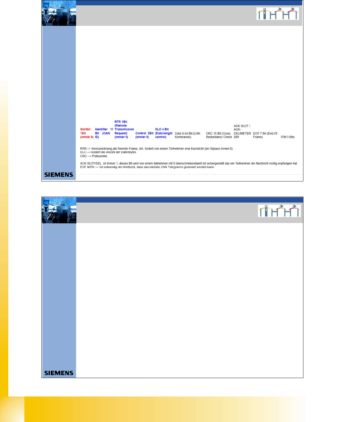
Aufbau CAN Telegramm (Beispiel)
ID 0x2 43 DLC 0x0 3 DATA 0x00 0x00 0x90
SOF ID RTR CONTROL /DLC DATACRC CR C-DELIMETER ACK–SLOT ACK-DELIMETER EOF ITM
0 01001000011 0 0000S11 0000 0S000 00S00 000S0 1001 0000 0S00011110110101 1 1 1 1111111 111
SOF 1Bit always 0
ID 11Bit 0/1
RTR 1Bit always 0 at SIPLACE
CONTROL 2Bit always 0 at SIPLACE
DLC 4Bit 0/1
DATA 0-64bit 0/1
CRC 15Bit 0/1
CRCDEL 1Bit 1
ACK-SLOT 1Bit 1 ; if 0 no subsystem can received this co mmand
ACK-DEL 1Bit 1
EOF 7Bit 1
ITM 3Bit 1
Î nächster SOF
2. CAN BUS Siplace
12Datum06/2008 Version 03 CAN Bus Workshop Mathias Michel
SIPLACE Campus
Automation and Drives
2. Error Frames
Error Frames
What are error frames?
Error frames are sent by the individual subsystems, when a command does not adhere to the encoding
rules or has been physically corrupted.
This occurs when a CAN telegram shows the same RxD level (low) for 6 or more consecutive bits
(logic 0 = dominant).
If a subsystem recognizes this type of command, it will immediately notify all other subsystems and the
transmitter of the telegram, by sending error frames.
After receiving an error frame, the other subsystems will reject the message (telegram) and send their own
error frames telegram. Once the bus is free again, the command will be resent.
The CAN Test Box is used to check the CAN network for error frames.
An accumulation of error frames indicates possible physical bus errors. If too many error frames are
recognized during operation, you will need to analyze the CAN signals in detail.
Note: Number of error frames during 4h placement operation < 10
2. Error Frames
1 - 9
Student Guide CAN BUS Workshop
Edition 06/2008 3 CAN BUS
9
13Datum06/2008 Version 03 CAN Bus Workshop Mathias Michel
SIPLACE Campus
Automation and Drives
3. Physikalische Überprüfung des CAN Bus
Signals on the different connectors
Differences:
Siplace HF: - Take out 24V from the CAN Bus
Retrofit kit number(00194610-01)
- TI 2005-08E03 CAN I/O Module Version 02
Siplace X: - Changing the 24 V power supply
- One Wire with CAT5 cable (00194705-01)
- One Wire (CAT 5) control only Temperatur
sensors
• CAN_INT - not used (+5V/ min. 4V)
• Power Fail - to storage the head specific data
(+5V/ min. 4V)
• CAN RESET - not used on HF and X machine
(+5V/ min. 4V)
• CAN HIGH - 2,5 +/- 0,3 V recessive Level
(When there is no communication on the Can Bus)
• CAN LOW - 2,5 +/- 0,3 V recessive Level
(When there is no communication on the Can Bus)
• CAN GND - Ground Can Bus
• Vcc 24V - was the 24V for the nozzle changer before.
• One wire - Only on the HF machine in the
CAN Bus cable
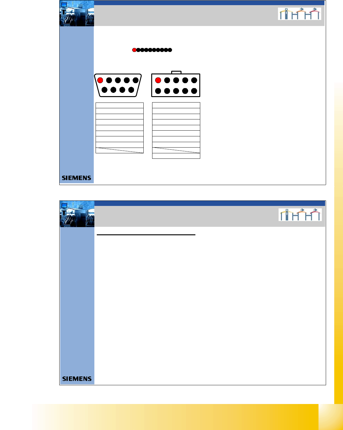
3. Checking the physical function
of the CAN BUS
9- pol Sub D
2 3 4 5
7 8 9
1
6
2
3
4
5
1
10 - Pin connector
7
8
9
10
6
2
3
4POWER_FAIL
5
CAN_INIT
6
CAN_GND
CAN_GND
7 CAN_HIGH
8
CAN_LOW
CAN-RESET
9 Vcc One_Wire (+24 V)
ONE_Wire
1
(+5V ) LOW_ ACTIVE
3
5
7POWER_FAIL
9
CAN_INIT
2
CAN_GND
CAN_GND
4CAN_HIGH
6
CAN_LOW
CAN-RESET
8 Vcc One_Wire (+24 V)
10
ON E_Wire
1
NC
(+5V) LOW_ ACTIVE
1 One_Wire
2 CAN_GND
3 CAN_LOW
4 CAN_HIGH
5 CAN_GND
6 CAN_RESET
7 Power_FAIL
8 Vcc_One_Wir e (+24V)
9 CAN_IN IT
10 NC
1 2 3 4 5 6 7 8 9 10
10 Wi re flat cable
Description Flat cable
Description 10 pi n co nnectorDescription 9 sub D co nn ector
14Datum06/2008 Version 03 CAN Bus Workshop Mathias Michel
SIPLACE Campus
Automation and Drives
1. Check the terminating resistors
Attention: To measure the terminating resistors you have to SWITCH OFF the machine!
To avoid reflection in the CAN lines, a 120 Ohm terminating resistor must be placed at each
end of the CAN bus wire, between CAN_H and CAN_L.
A correctly closed CAN bus will have a resistance value of 60 Ohm.
An additional terminating resistor reduces the overall resistance to 40 Ohm. (1/Rges.= 1/R1+1/R2+.....)
If the resistors are not placed at the end points, the CAN lines will experience reflections.
The effect of incorrect terminating resistors can be seen in the appropriate diagram in this .ppt.
Measure: Between Pin 2 and 7
Nominal value: 60 O
For the positions of the terminating resistors,
refer to Chapter CAN Bus Operation Diagrams in the manual CAN Test Box
3. Überprüfung der Abschlußwiderstände
3. Checking the terminating resistors
1 - 10
Student Guide CAN BUS Workshop
3 CAN BUS Edition 06/2008
10
15Datum06/2008 Version 03 CAN Bus Workshop Mathias Michel
SIPLACE Campus
Automation and Drives
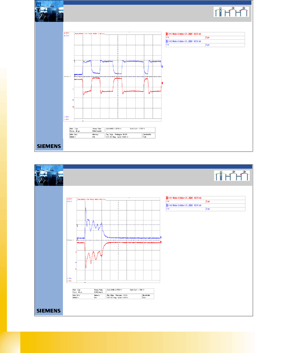
3. Auswirkung der Abschlußwiderstände
Terminating Resistors 60 Ohm Æ OK
CAN High - level approx. 1,5V
CAN Low – Level approx. 1,5 V
3. Effect terminating resistors
16Datum06/2008 Version 03 CAN Bus Workshop Mathias Michel
SIPLACE Campus
Automation and Drives
3. Auswirkung falscher Abschlußwiderstände
Terminating Resistors 120 Ohm
CAN High - Level
CAN Low - Level
3. Effect wrong terminating resistors