CAN Bus Workshop_Version 03__06-2008_EN.pdf - 第236页
1 - 28 Siplace C AN T est Box 1 CAN T est Box Edition 04/200 8 28 1.10.5.2 HF CAN Bus Structures wit h Old Cable Harness and KSP 352 (SW504) CAN bus st ructure with SW 504.xx and COM asse mbly KSP 352; with old cable har…
1 - 27
Siplace CAN Test Box
Edition 04/2008 1 CAN Test Box
27
1.10.5 CAN Bus Structure for HF
1.10.5.1 General Differences
The HF machines will have the following differences:
– Communication assemblies 2x KSP 352 or one KSP 354
– HF machines with one CAN BUS for both placement areas are only supported by station soft-
ware versions 504.xx
– HF machines from station software version 505.xx only support the CAN bus structure with
one CAN bus per placement area.
– A difference is made between old and (new) universal cable harnesses.
This has the following consequences: 1
When checking or replacing the communication assemblies, always observe the terminating re-
sistors. Make sure you perform a physical check!
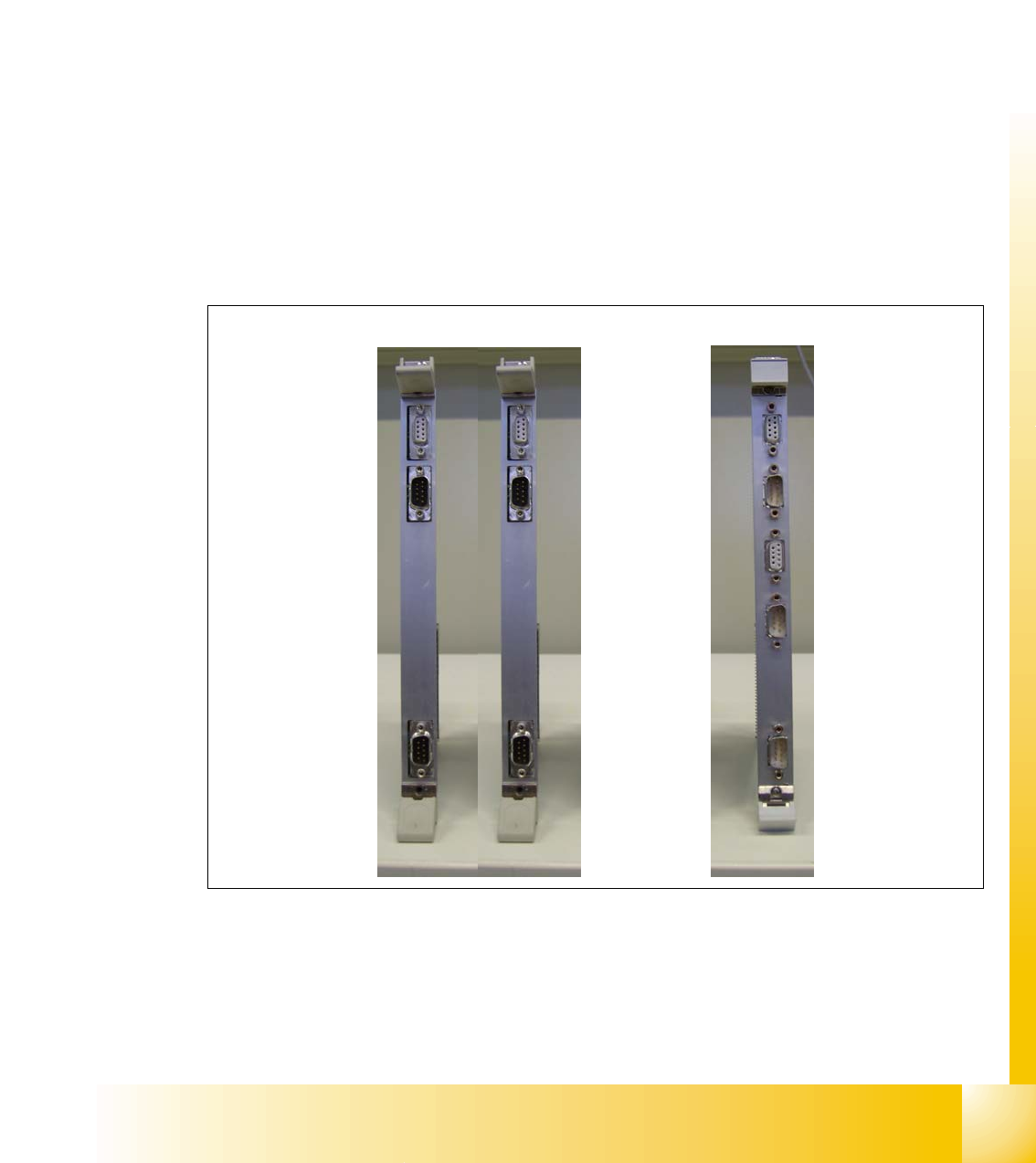
Fig. 1.10 - 6 KSP 352 and KSP 354 communication assemblies
COM KSP 354
COM KSP 352
X6
X7
X7
X6
X11
X12
X7
X6
1 - 28
Siplace CAN Test Box
1 CAN Test Box Edition 04/2008
28
1.10.5.2 HF CAN Bus Structures with Old Cable Harness and KSP 352 (SW504)
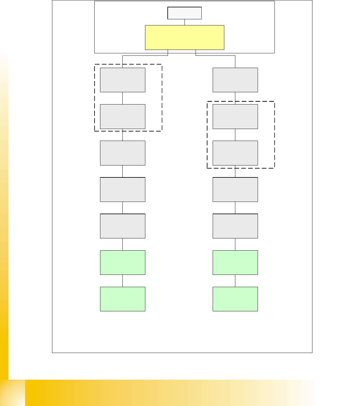
CAN bus structure with SW 504.xx and COM assembly KSP 352; with old cable harness (labeling
on cable = 0300xxxx-0x); one CAN bus for both placement areas.
Fig. 1.10 - 7 HF CAN bus structure (one CAN bus with old cable harness, KSP 352 and SW 504)
SMP BUS
C
O
M
U
n
i
t
K
S
P
3
5
2
(
l
e
f
t
C
o
m
U
n
i
t
)
MC
Axis unit
PA 2
Trailing cable-
Interface
Gantry 1
Trailing cable-
Interface
Gantry 2 *
CAN Bus cable 2
CAN E/
A
Modu
l
Sektor
4
CAN E/
A
Modu
l
Sektor
4
CAN E/
A
Modu
l
Sektor
4
CAN I/O
SUB Module
Section 4
Vision
Section 2
COT 2 / MTC
Tape cutter
Transpor
t
Control
unit
Vision
Control unit
CAN I/O
Main Module
COT 1
Tape cutter
COT 3
Tape cutter
COT 4 / MTC
Tape cutter
CAN Bus cable 1
Computer Unit
SUB Distributor Section 2
Main Distributer Sektor 4
Section 4
Control unit
Section 2
One CAN Bus !
* after SW Update 504 --> 505 Gantry 2 will be changed to
gantry 3 and two CAN Bus!
old Trailling cable
old circuit diagram!
x7pnx6pn
Head board(C500)
Gantry 1
Terminator
(120 OHM)
Head board(C500)
Gantry 2 *
Terminator
(120 OHM)
1 - 29
Siplace CAN Test Box
Edition 04/2008 1 CAN Test Box
29
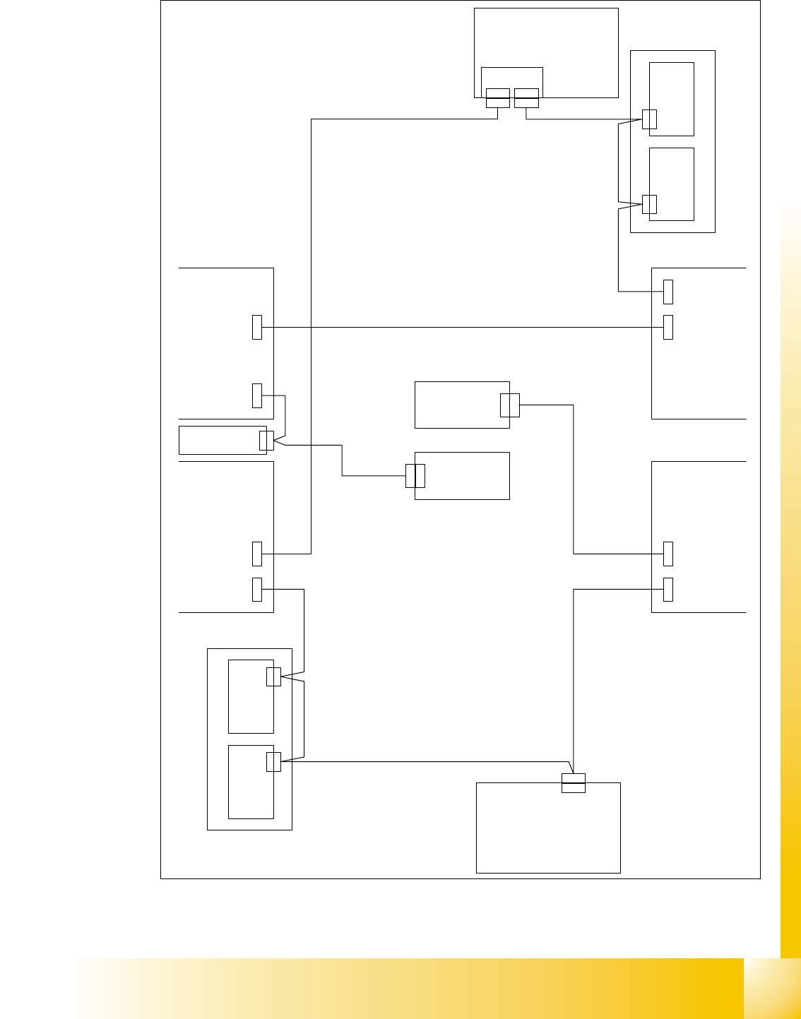
Fig. 1.10 - 8 HF CAN bus structure (one CAN bus with old cable harness, KSP 352 and SW 504)
X 2 r d
C A N
C A N I / O - M o d u l
0 0 3 5 5 0 5 1 ( r b )
X 1 r b
C A N
S u b D i s t r i b u t o r
0 3 0 0 1 5 3 2 ( r a )
X 2 r d X 1 r b
V i s i o n C o n t r o l - U n i t
0 0 3 6 3 9 6 1 ( q d )
C A N
M a i n D i s t r i b u t o r
0 3 0 0 1 5 3 1 ( q a )
X 2 q d
X 2 q d
C A N
X 1 q b
X 1 q b
A x i s U n i t 0 3 0 1 3 9 7 0
C o m p u t e r U n i t
0 3 0 0 2 1 1 0
S c h l e p p I n t e r f a c e
P 1 0 0 3 5 3 5 9 3
X 4 0 a a
C A N
( a a )
S c h l e p p I n t e r f a c e
P 2 0 0 3 5 3 5 9 3
X 4 0 b a
C A N
( b a )
E i n z u g 2 E i n z u g 1
E i n z u g 3 E i n z u g 4
C O M - B g . l i n k s
X 9 s q
C A N
X 9 s q
X 4 0 b a
X 4 0 a a
X 7 p nX 6 p n
X 1 2 5X 1 2 6
C A N - I nC A N - O u t
X 1 1 5X 1 1 6
C A N - I nC A N - O u t
X 1 3 5 X 1 3 6 X 1 4 5X 1 4 6
C A N - I n C A N - O u t C A N - I nC A N - O u t
C A N
L P - S t e u e r u n g
X 2 2 a o
C A N - B u s 1 : C o m p u t e r U n i t - E i n z u g 2
0 3 0 0 3 5 6 0
C A N - B u s 1 :
E i n z u g 2 - M a i n D i s t . - A x i s U n i t - E i n z u g 3
0 3 0 0 3 5 6 1
C A N - B u s 1 : E i n z u g 3 - S c h l e p p I n t e r f a c e
0 3 0 0 3 5 6 2
C A N - B u s 2 : E i n z u g 4 - E i n z u g 1
0 3 0 0 3 5 6 4
C A N - B u s 2 :
E i n z u g 1 - L P - S t e u e r u n g - S c h l e p p I n t e r f a c e
0 3 0 0 3 5 6 5
C A N - B u s 2 : C o m p u t e r U n i t - S u b D i s t r . - E i n z u g 4
0 3 0 0 3 5 6 3
X 7 p nX 6 p n
C A N I / O - M o d u l
0 0 3 5 5 0 5 1 ( q b )
V i s i o n C o n t r o l - U n i t
0 0 3 6 3 9 6 1 ( r d )
X 2 2 a o
SIPLACE HF with old cable harness
A
ctual CAN-Bus-wiring