CAN Bus Workshop_Version 03__06-2008_EN.pdf - 第69页
1 - 7 S tudent Guide CAN BUS W orkshop Edition 06/20 08 3 CAN B US 7 9 Datum 06 /20 08 Vers ion 0 3 CA N Bu s Wo rksh op M at hi a s Mic h el SIPL ACE Cam p us Aut om atio n and D rive s 2. A u fbau C AN I D `s 2. Co ns …
1 - 6
Student Guide CAN BUS Workshop
3 CAN BUS Edition 06/2008
6
7Datum06/2008 Version 03 CAN Bus Workshop Mathias Michel
SIPLACE Campus
Automation and Drives
2. Aufbau CAN Telegramm (allgemein)
2. Construction CAN telegram
Start
Control
information
Data (0-8 Bytes user
information)
CRC
End
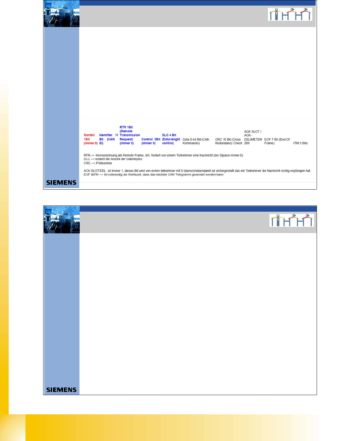
Start:Start: determines the telegram start. After this Bit is set, no other user of the Can Bus is able to
send.
Even 2 or more user set this bit at the same time, the arbitration decides the highest priority. The
address with the highest priority is allowed to send the telegram.
Address: Identifier field:
The value of this number is also the priority for bus access. The lowest number has the higher priority
Control information/DLC
Contains reserved bits and 4 bit DLC. The DLC (data length code) shows, how many Bytes are
transferred with the data field
CRC Sequence + CRC Delimiter = CRC Field (Cyclic Redundancy Check)
Each message is combined with a CRC word. Therefore it recognizes messages which are at least not
in an origin state while disturbances
End
The length of the end recognition is 7 Bit
Address
(11 Bit Identifier)
8Dat um06/2008 Version 03 CAN Bus Workshop Mathias Michel
SIPLACE Campus
Automation and Drives
Multi master:
When the bus is free any unit may start to transmit a message. The unit with the
message of the highest priority is transmitted at first.
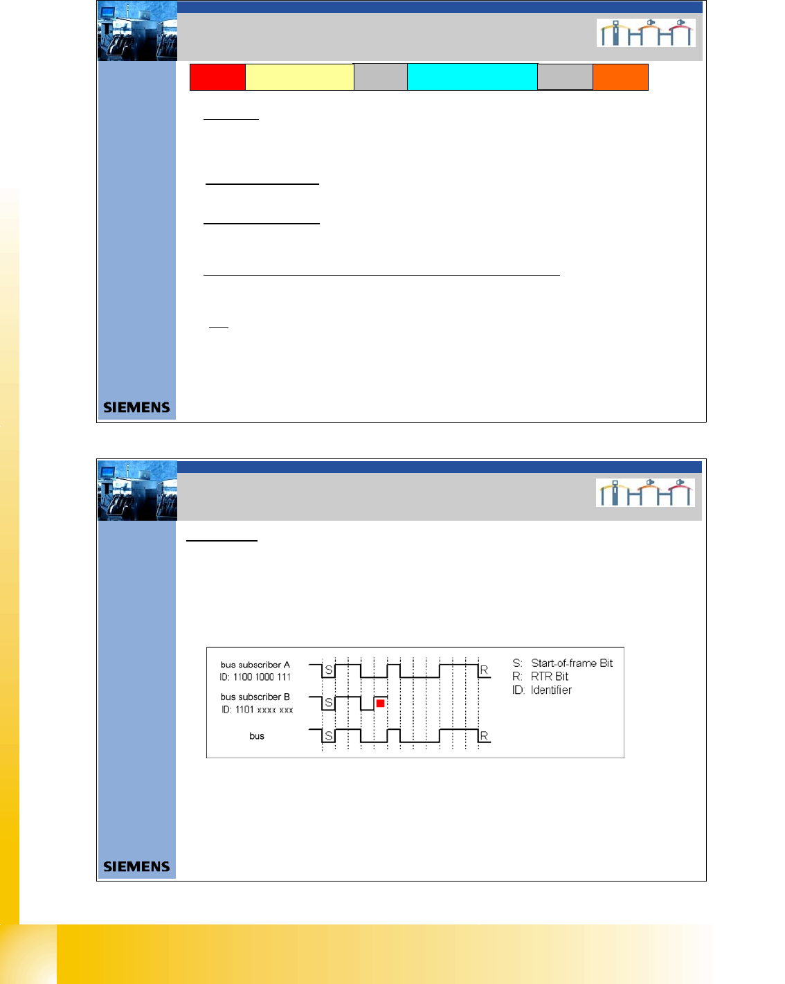
Arbitration:
Whenever the bus is free, any unit may start to transmit a message. If 2 or more units start
transmitting messages at the same time, the bus access conflict is resolved by bitwise
arbitration using IDENTIFIER.
If the user A and B want to transmit a message, they begin to do after the start-of-frame bit
and compare in each case the bits sent and received. Since"0" dominates on the bus, user
B recognizes that the fourth bit is different from the bits sent and leave his message. User
B is waiting that the bus will free until the next Start-of-frame. User A recognize no different
and send continuous the message. Messages with high Priority have an Identifier, with a lot
of "0" bits.
There are two bus states possible during arbitration: dominant and recessive.
2. CAN BUS Arbitration
2. CAN Bus Arbitration

1 - 7
Student Guide CAN BUS Workshop
Edition 06/2008 3 CAN BUS
7
9Datum06/2008 Version 03 CAN Bus Workshop Mathias Michel
SIPLACE Campus
Automation and Drives
2. Aufbau CAN ID`s
2. Construction of the CAN ID`s
10 3456789 012
Channel
00 CMD = Comman d
01 ACK =Acknowledg e
10 DBG = Debugg
11 PUB = Public
Direction
0 - The Object send your own
Objekt Number.
1 - Message send the Objekt
Number which subsystem
have to received this
massege
Gantry
00 Gantry 1
01 Gantry 2
10 Gantry 3
11 Gantry 4
Object ID
- Head - Vision Objects
- Axis objects
- Component handling
- Tr ansport
- Safety
0 0000011 000
Example Head processor CAN ID 300 (hex)
Gantry 1
0 1000011 000
Example Head processor CAN ID 308 (hex)
Gantry 2
0 0100011 000
Example Head processor CAN ID 310 (hex)
Gantry 3
0 1100011 000
Example Head processor CAN ID 318 (hex)
Gantry 4
11 Bit Identifier
10Datum06/2008 Version 03 CAN Bus Workshop Mathias Michel
SIPLACE Campus
Automation and Drives
2. Aufbau CAN ID`s
2. Calculate CAN ID
0 1100011 000
Determine CAN ID
10 3456789 012
11 bit Identifier
Binär: 2 hoch X
1024 8163264128256512 124
0 816000256512 000
The result i s decimal 792 Æ calculate to HEX you get 31 8.
Variant 1:
Variant 2:
divide the Identifier into 4 bit block,
that way you get the HEX number easy
2 3012301 012
Binär: 2 hoch X
4 8124812 124
0 1100011 000
Excample Headprocessor
CAN ID 318 (hex)
Gantr y 4
0 8100012 000
Add the block you get directly the HEX number 318.
2 hoch X calculated
11 bit Identifier
Add block wise
31 8
Excample Headproc essor
CAN ID 318 (hex)
Gantry 4
1 - 8
Student Guide CAN BUS Workshop
3 CAN BUS Edition 06/2008
8
11Dat um06/2008 Version 03 CAN Bus Workshop Mathias Michel
SIPLACE Campus
Automation and Drives
Aufbau CAN Telegramm (Beispiel)
ID 0x2 43 DLC 0x0 3 DATA 0x00 0x00 0x90
SOF ID RTR CONTROL /DLC DATACRC CR C-DELIMETER ACK–SLOT ACK-DELIMETER EOF ITM
0 01001000011 0 0000S11 0000 0S000 00S00 000S0 1001 0000 0S00011110110101 1 1 1 1111111 111
SOF 1Bit always 0
ID 11Bit 0/1
RTR 1Bit always 0 at SIPLACE
CONTROL 2Bit always 0 at SIPLACE
DLC 4Bit 0/1
DATA 0-64bit 0/1
CRC 15Bit 0/1
CRCDEL 1Bit 1
ACK-SLOT 1Bit 1 ; if 0 no subsystem can received this co mmand
ACK-DEL 1Bit 1
EOF 7Bit 1
ITM 3Bit 1
Î nächster SOF
2. CAN BUS Siplace
12Datum06/2008 Version 03 CAN Bus Workshop Mathias Michel
SIPLACE Campus
Automation and Drives
2. Error Frames
Error Frames
What are error frames?
Error frames are sent by the individual subsystems, when a command does not adhere to the encoding
rules or has been physically corrupted.
This occurs when a CAN telegram shows the same RxD level (low) for 6 or more consecutive bits
(logic 0 = dominant).
If a subsystem recognizes this type of command, it will immediately notify all other subsystems and the
transmitter of the telegram, by sending error frames.
After receiving an error frame, the other subsystems will reject the message (telegram) and send their own
error frames telegram. Once the bus is free again, the command will be resent.
The CAN Test Box is used to check the CAN network for error frames.
An accumulation of error frames indicates possible physical bus errors. If too many error frames are
recognized during operation, you will need to analyze the CAN signals in detail.
Note: Number of error frames during 4h placement operation < 10
2. Error Frames