CAN Bus Workshop_Version 03__06-2008_EN.pdf - 第149页
CACCIA Manual 1 Caccia Student Guide Issue 04/2007 EN 57 Fig. 1 - 33 Adapter card for axis card A364 → Switch on the boot strap switch 1 resp. 2 to ON. See (1) - switch 1 for both axes above (A1, A2) and switch 2 for bot…
1 Caccia Student Guide CACCIA Manual
Issue 04/2007 EN
56
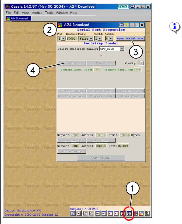
Fig. 1 - 32 A24-Download
→ Click on
Serial Firmware Download.
→ The A24 Download dialog appears.
NOTE:
For
Serial Port Properties
no
settings are necessary. The default
settings can be accepted.
Key
1. Icon
Serial Firmware Download
2. A24-Download-dialog
3. Button
Open Serial Port
4. Button
Start
CACCIA Manual 1 Caccia Student Guide
Issue 04/2007 EN
57
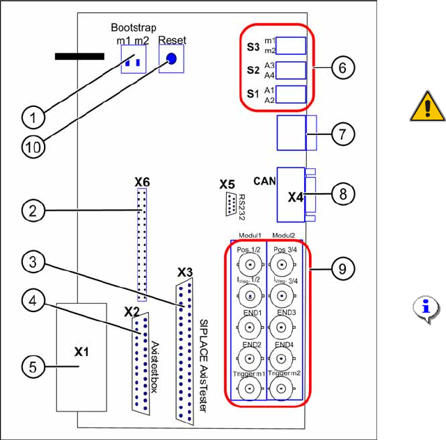
Fig. 1 - 33 Adapter card for axis card A364
→ Switch on the bootstrap switch 1 resp. 2 to
ON. See (1) - switch 1 for both axes
above (A1, A2) and switch 2 for both axes
below (A3, A4).
ATTENTION:
Only one of the switches must be
set to ON, that means bootstrap
switch 1 for A1/A2 or switch 2 for
the axes A3/A4.
→ Press the reset switch. Both processors
will be reset.
→ Click in CACCIA on the button
Open Se-
rial Port
and subsequenty the button
Start
.
NOTE:
The activation of the reset-switch
and the button
Open Serial Port
and
Start
must follow within
10 sec., otherwise no
communication will be established.
1 Caccia Student Guide CACCIA Manual
Issue 04/2007 EN
58
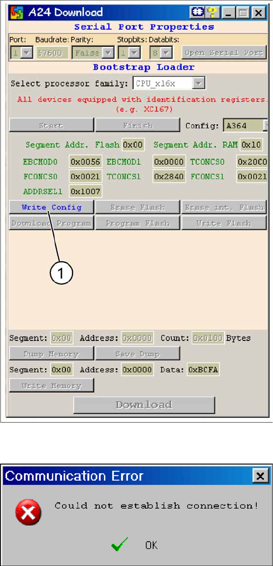
Fig. 1 - 34 A24 download dialog: Connection to axis card is OK
In case of a succesful connection the
adjoined window is displayed.
→ Click on button
Write Config
(1).
Fig. 1 - 35 Error message during establishing V24 connection
In case of a connection failure the adjoined
error message is shown.
→ In this case repeat the sequence descri-
bed above.
→ Close the window and reopen it.
→ Press reset switch on the adapter card.
→ Cick in CACCIA on the button
Open Se-
rial Port
and subsequently on the button
Start
.