CAN Bus Workshop_Version 03__06-2008_EN.pdf - 第290页
1 - 82 Siplace C AN T est Box 1 CAN T est Box Edition 04/200 8 82 Fig. 1.10 - 58 CAN bus structure D2 operation diagram 03043798- 010302LD3 C A N T e r m i n a t i o n o n : S 1 . 8 = O N C A N T e r m i n a t i o n o n …
1 - 81
Siplace CAN Test Box
Edition 04/2008 1 CAN Test Box
81
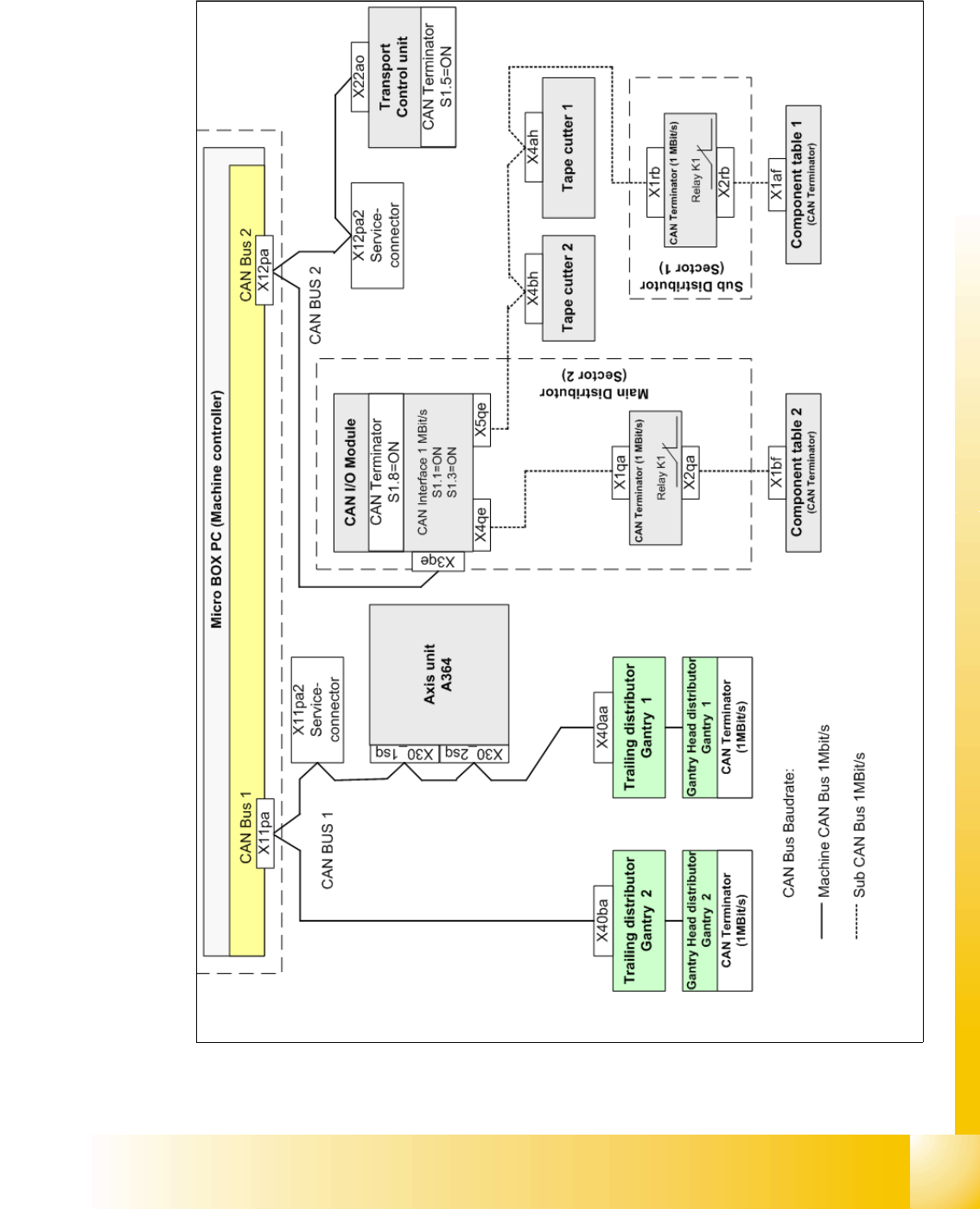
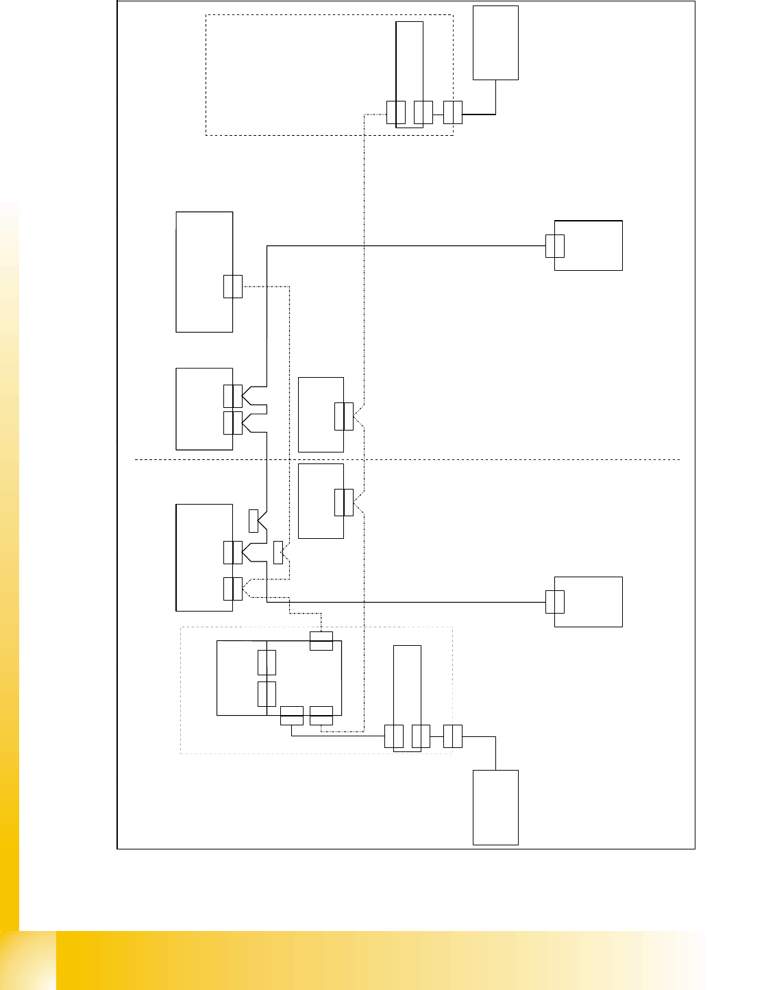
1.10.10.2 CAN Bus Siplace D2
Fig. 1.10 - 57 CAN bus structure D2
1 - 82
Siplace CAN Test Box
1 CAN Test Box Edition 04/2008
82
Fig. 1.10 - 58 CAN bus structure D2 operation diagram 03043798-010302LD3
C A N T e r m i n a t i o n o n :
S 1 . 8 = O N
C A N T e r m i n a t i o n o n :
S 1 . 5 = O N
f i x e d C A N T e r m i n a t i o n o n
G a n t r y H e a d D i s t r i b u t
o r
0 3 0 3 8 0 0 2
f i x e d C A N T e r m i n a t i o n o n
G a n t r y H e a d D i s t r i b u t o r
0 3 0 3 8 0 0 2
C A N I / O m o d u l e
0 0 3 5 5 0 5 1 ( q b )
B E - T i s c h 2
C o m p o n e n t s t a b l e 2
0 3 0 4 1 3 1 5 )
M a s c h i n e n C o n t r o l l e r
M a c h i n e c o n t r o l l e r
0 3 0 3 2 3 4 2 ( p a )
C A N - B U S 1 D 2
A x i s U n i t A 3 6 4
0 3 0 4 2 0 4 7
T r a n s p o r t s t e u e r u n g T S P 2 0 1
C o n v e y o r c o n t r o l l e r T S P 2 0 1
0 3 0 4 3 8 3 2
C A N 2 C A N 1
X 2 2 a o
X 2 2 a o
X 3 0 _ 1 s q
X 3 0 _ 1 s q
X 1 1 p aX 1 2 p a
X 1 1 p a
X 1 b f
H a u p t v e r t e i l e r
M a i n D i s t r i b u t o r
0 3 0 5 0 1 7 8 ( b f )
U n t e r v e r t e i l e r
S u b D i s t r i b u t o r
0 3 0 5 0 1 7 7 ( a f )
S c h l e p p -
V e r t e i l e r
T r a i l i n g
d i s t r i b u t o r
0 3 0 3 8 6 9 0
X 4 0 b a
X 4 0 b a
X 1 b f X 1 a f
X 1 a f
X 3 0 _ 2 s q
X 3 0 _ 2 s q
0 3 0 5 0 1 6 3
X 1 1 p a 2 S e r v i c e
P o r t a l 2 / G a n t r y 2
S e k t o r 2
S e c t o r 2
S e k t o r 1
S e c t o r 1
C A N - B U S 2 S u b
0 3 0 5 0 1 6 5
X 1 q b
X 1 q e
C A N - I n t e r f a c e
0 3 0 3 2 3 4 6 ( q e )
X 4 b h
X 4 b h
X 3 q e
X 3 q e
X 5 q e
X 5 q e
X 4 q e
X 4 q e
G u r t s c h n e i d e r 2
T a p e c u t t e r 2
0 3 0 0 6 4 1 1 ( b h )
G u r t s c h n e i d e r 1
T a p e c u t t e r 1
0 3 0 0 6 4 1 1 ( a h )
X 1 r b
X 1 r b
X 2 r b
X 2 r b
B E - T i s c h 1
C o m p o n e n t s t a b l e 1
0 3 0 4 1 3 1 5
C A N - B U S t e r m i n a t o r
c o m p o n e n t t a b l e
0 3 0 4 6 8 6 3
X 4 a h
X 4 a h
X 1 q a
X 1 q a
X 2 q a
X 2 q a
C A N - B U S t e r m i n a t o r
c o m p o n e n t t a b l e
0 3 0 4 6 8 6 3
X 2 q b
X 2 q e
S c h l e p p -
V e r t e i l e r
T r a i l i n g
d i s t r i b u t o r
0 3 0 3 8 6 9 0
X 4 0 a a
X 4 0 a a
P o r t a l 1 / G a n t r y 1
X 1 2 p a 2 S e r v i c e
X 1 2 p a
C A N - B U S 2 D 2
0 3 0 5 0 6 6 6
1 - 83
Siplace CAN Test Box
Edition 04/2008 1 CAN Test Box
83
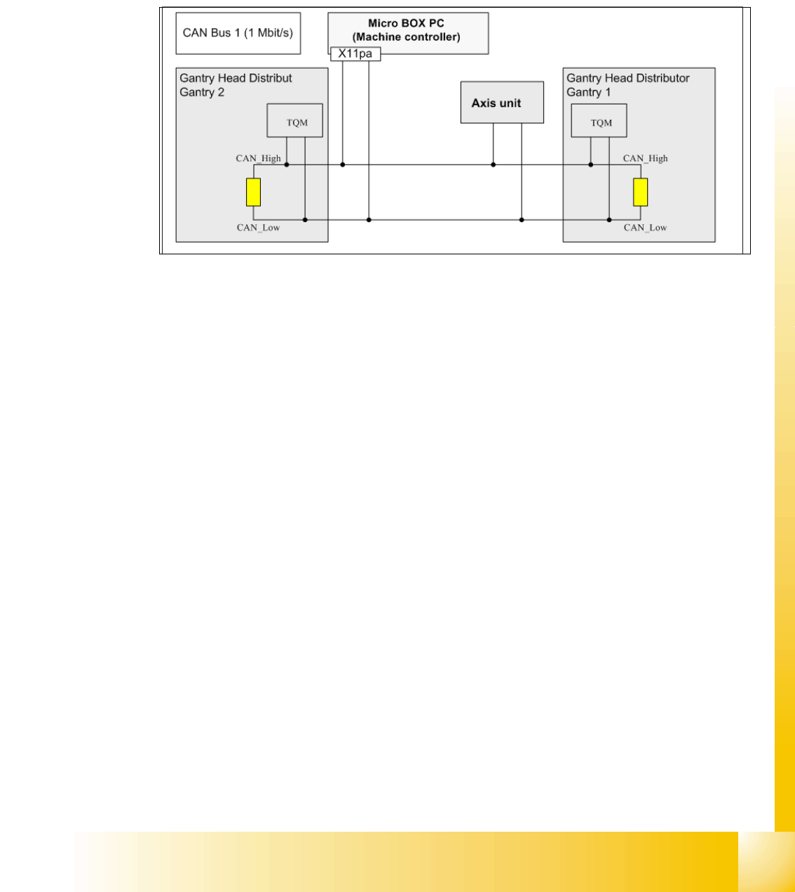
CAN Bus with CAN Terminator on the D2 in detail 1
For the D2 machine we use two different CAN BUS circuits. CAN BUS 1 is working with 1 MBit/s
and CAN BUS 2 is cut in to areas with a different speed. One part of the CAN BUS 2 works with
1Mbit/s and the CAN BUS for the component table and tape cutter with 500 kbit/s. The speed of
the CAN BUS 2 will be reduce on the CAN Interface board which is located on the CAN I/O module
Fig. 1.10 - 59 CAN BUS 1 on the D2 machine
Note to measure the CAN terminator:
In General, the terminator has to measure if the machine is switch off!
In the Fig. 1.10 - 59 for the CAN BUS 1, there are two terminators in the circuit, When the machine
is switch off you have to measure on the serviceconnector X11pa2 a value of 60 Ohm.