CAN Bus Workshop_Version 03__06-2008_EN.pdf - 第20页
1 - 12 S tudent Gu ide CAN BUS Wor kshop 1 Operat iona l safety Editi on 06/2 008 12 1.3.1.3 Des cription of the funct ions Main power switch in the OFF position (items 1 in Fig. 1. 3 - 1 1 The main power switch d isconn…
1 - 11
Student Guide CAN BUS Workshop
Edition 06/2008 1 Operational safety
11
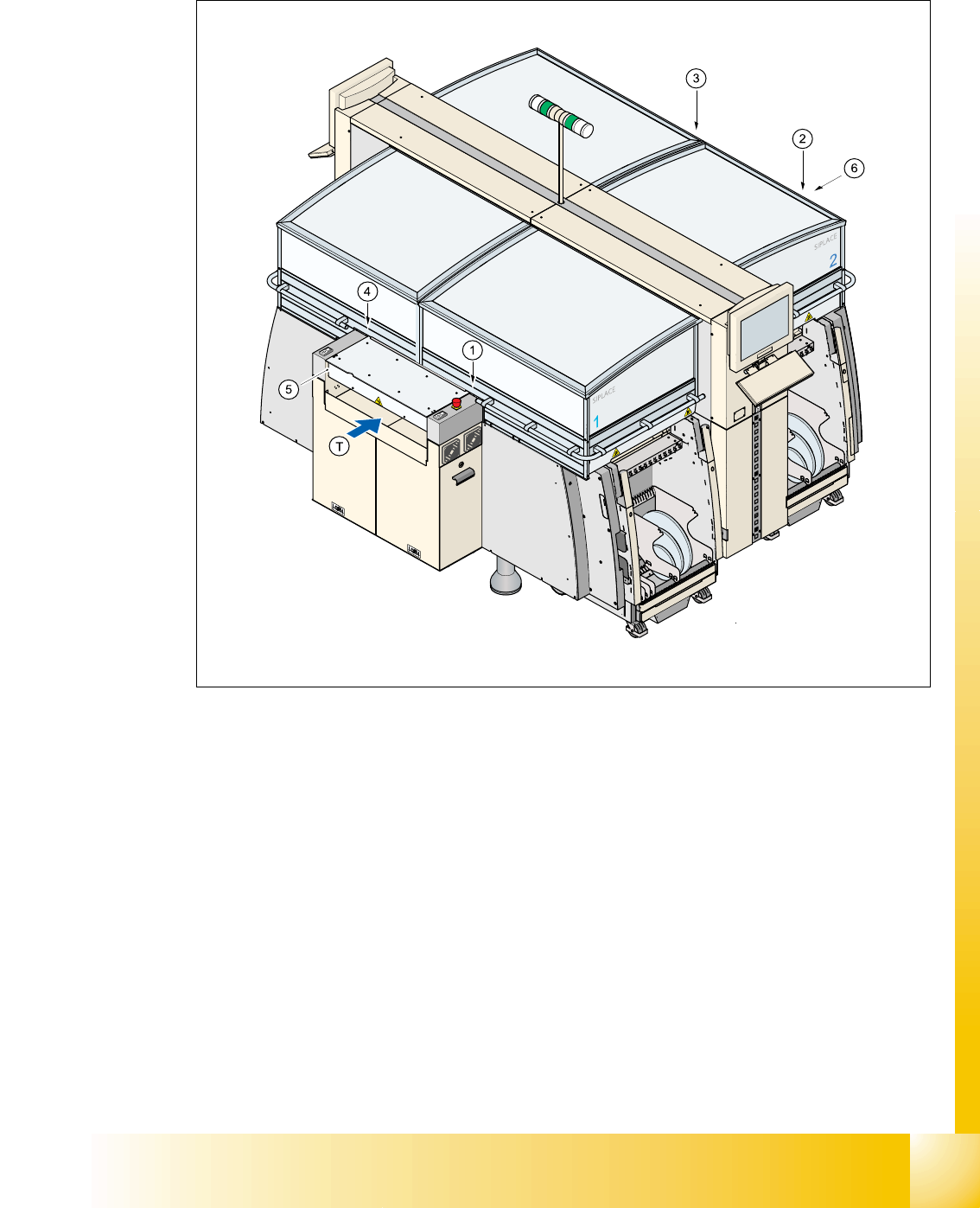
1.3.1.2 Position of protective switches on the placement machine
Fig. 1.3 - 2 Position of protective switches on the placement machine
1. Protective cover switch, location 1
2. Protective cover switch, location 2
3. Protective cover switch, location 3
4. Protective cover switch, location 4
5. Protective switch for the cover on the input side of the PCB conveyor
6. Protective switch for the cover on the output side of the PCB conveyor
(T) PCB transport direction

1 - 12
Student Guide CAN BUS Workshop
1 Operational safety Edition 06/2008
12
1.3.1.3 Description of the functions
Main power switch in the OFF position (items 1 in Fig. 1.3 - 1 1
The main power switch disconnects the three phases L1, L2, and L3 from the power supply.
WARNING 1
The following components still carry potentially lethal voltages even if the main power switch is
switched off:
– Cable connection terminals 1, 3, and 5 of the S1 main power switch
– Mains filter Z1
– Service socket X102
– F1 automatic circuit breaker for the service socket
– The color of all individual wires, which still carry potentially lethal voltages even if the main
power switch is switched off, is brown.
➠ Death, serious injury or considerable damage may result if these automatic placement sys-
tems are handled incorrectly.
➠ Always follow the applicable accident prevention and DIN regulations (particularly DIN EN 60
204, part 1) and the applicable regulations in your own country.
➠ The safety door to the power supply must ONLY be opened by appropriately qualified and
trained personnel.
Emergency stop push-button (item 5 in Fig. 1.3 - 1) 1
The emergency stop push-button is red and latches in the ON position when pressed. When you
press the emergency stop push-button the switching contact of the safety circuit opens and the
protective contactor combination (PCC K6) trips. The link voltage (250 VDC) for the gantry axes
and the link voltage (145 VDC) for the star axes is switched off. The servo amplifiers for the DP
and Z axes are still supplied with 40 VDC. The signaling contact of the emergency stop push-but-
ton closes and the message "emergency stop pressed" appears on the screen. The following
modules
– PCB conveyor
– PCB clamping
– width adjustment
– PCB stopper and the
– used tape cutter
are deactivated.
PLEASE NOTE Placement is interrupted and can then either be continued or canceled once the
machine is working correctly again.
1 - 13
Student Guide CAN BUS Workshop
Edition 06/2008 1 Operational safety
13
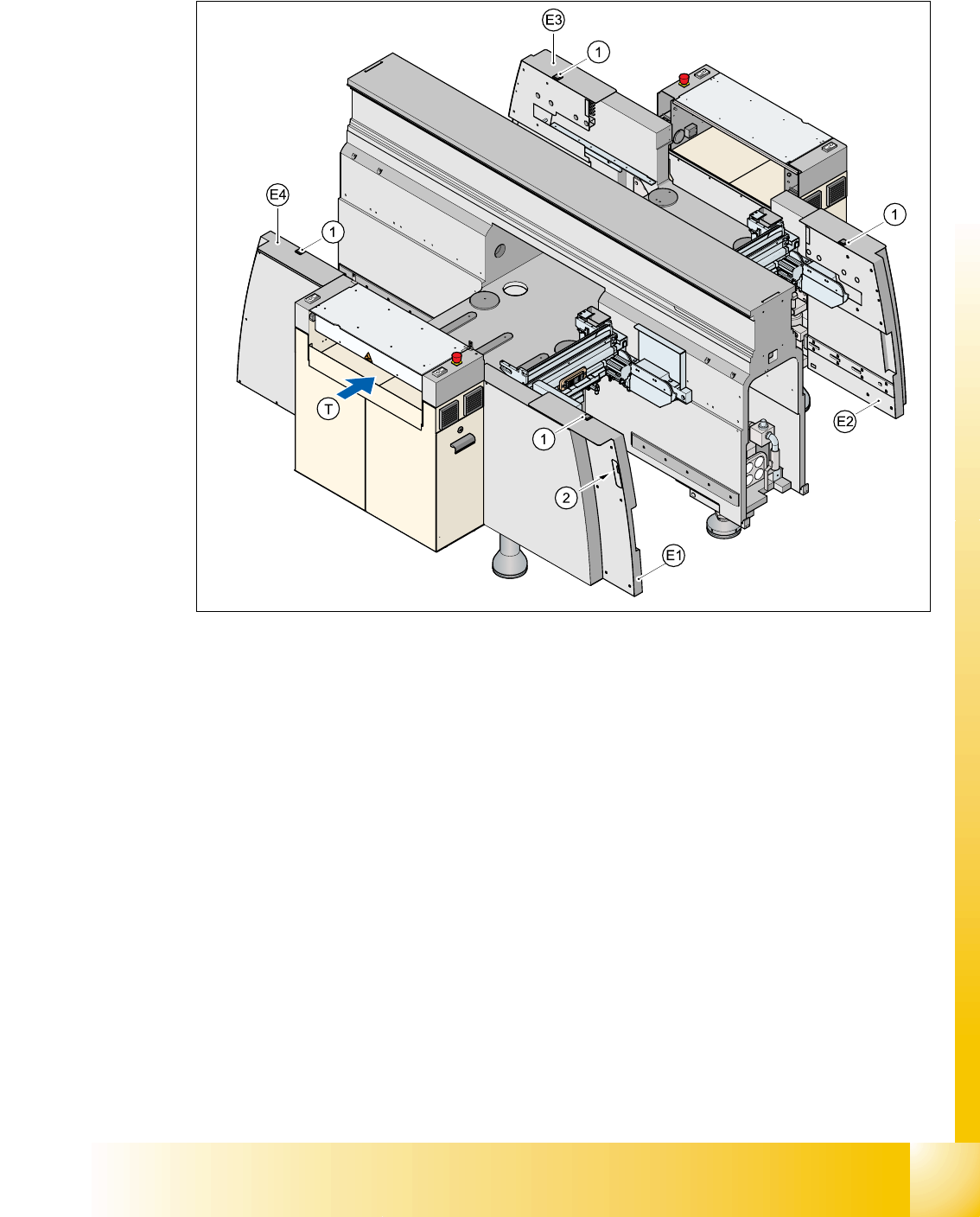
1.3.2 Position of the push-buttons for docking the component trolleys in and out
Fig. 1.3 - 3 Position of push-buttons on the component trolley
1. Push-button on the top
2. Push-button in the guard
E1guard, location 1
E2guard, location 2
E3guard, location 3
E4guard, location 4
Two push-buttons are integrated into the guard module (items E1, E2, E3 and E4). These are used
to dock the component trolley in or out at the location. These push-buttons must be pressed si-
multaneously, if you docking the component trolley.