CAN Bus Workshop_Version 03__06-2008_EN.pdf - 第53页
1 - 27 S tudent Guide CAN BUS W orkshop Edition 0 6 /2008 2 Comm unication and Control 27 X9_5 GND X9_6 GND X9_7 GND X9_8 GND Terminals I / O Description / Note

1 - 26
Student Guide CAN BUS Workshop
2 Communication and Control Edition 06/2008
26
2.2.8.5 I/O Module, Subdistributor (Outputs)
nc= not connected (Reserve)
X5_8 Di23 nc
X5_8 Di23 nc
X6_1 nc
X6_2 nc
X6_3 GND
X6_4 nc
X6_5 nc
X6_6 nc
X6_7 nc
X6_8 nc
Terminals I / O Description / Note
Terminals I / O Description / Note
X7_1 Do0 nc
X7_2 Do1 nc
X7_3 Do2 nc
X7_4 Do3 nc
X7_5 Do4 nc
X7_6 Do5 St_Vakuumpumpe EIN
X7_7 Do6 nc
X7_8 Do7 nc
X8_1 Do8 nc
X8_2 Do9 nc
X8_3 Do10 nc
X8_4 Do11 nc
X8_5 Do12
X8_6 Do13
X8_7 Do14
X8_8 Do15
X9_1 24 V
X9_2 24 V
X9_3 24 V
X9_4 24 V

1 - 28
Student Guide CAN BUS Workshop
2 Communication and Control Edition 06/2008
28
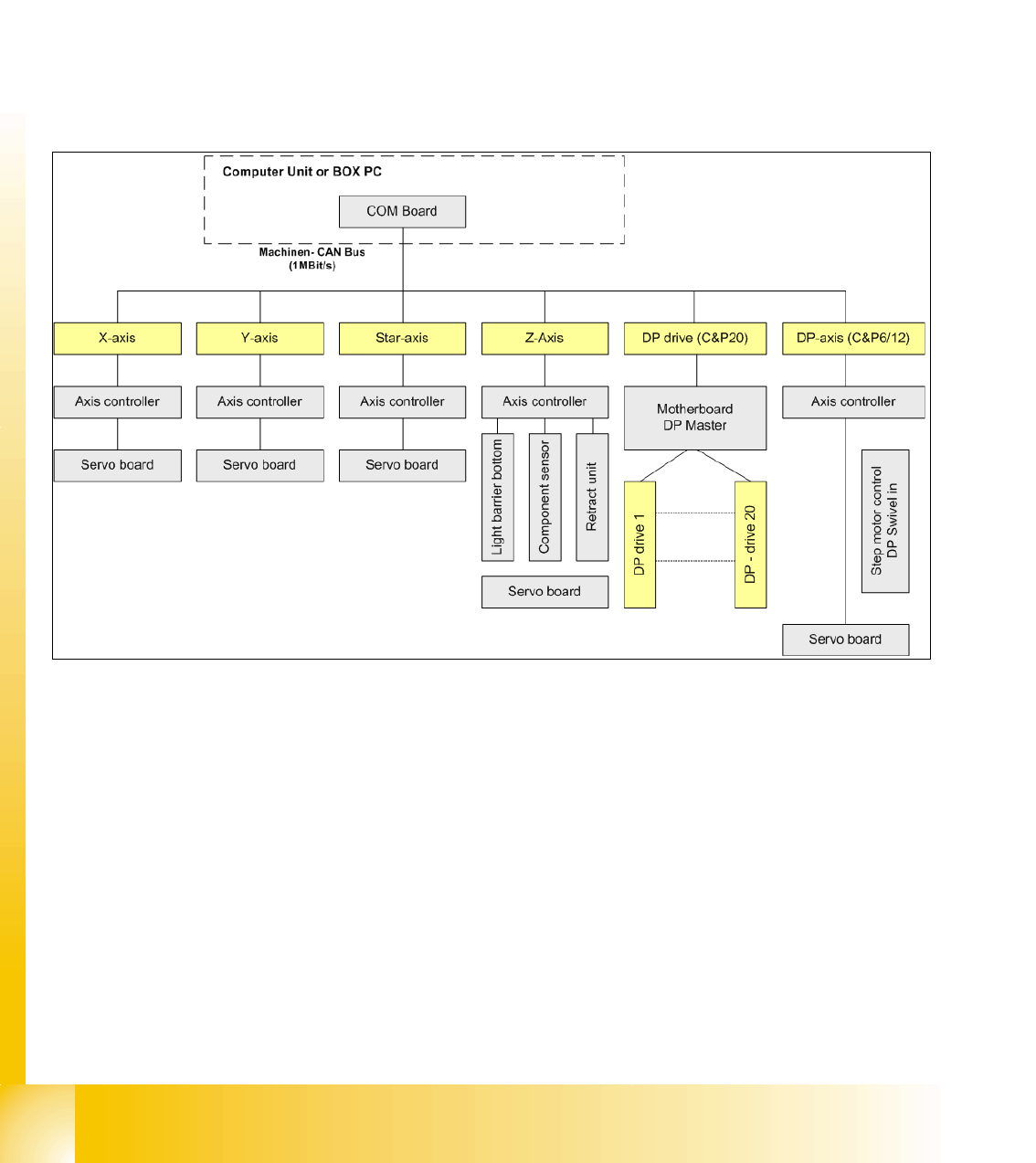
2.2.9 CAN: Bus Communication with Axis Controller
In previous Siplace placement machines, the communication and data flow between axis control-
ler and machine controller was achieved using the SMP bus. From the HF machine generation
on, the SMP bus is no longer used with the axis system.
The communication between the axis controller modules is now achieved using the CAN Bus. All
information, which has to be transfered between these modules, is now on the CAN bus (e.g axis
parameter, target position, end signal, ...) This of course means that the number of single tele-
grams increases significantly compared with the amount of data exchange which has occurred
previously.
Fig. 2.2 - 20 Overview axis controller