CAN Bus Workshop_Version 03__06-2008_EN.pdf - 第251页
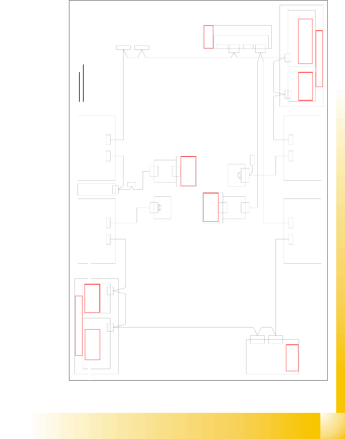
1 - 43 Siplace C AN T est B ox Edition 04 /2008 1 CAN T est Box 43 Fig. 1.10 - 22 HF CAN bus struct ure (one CAN b us per P A, universal cable harne ss, SW 505 version 2) Vision-Steuerung 00363 961 CAN Hauptverteiler 030…
1 - 42
Siplace CAN Test Box
1 CAN Test Box Edition 04/2008
42
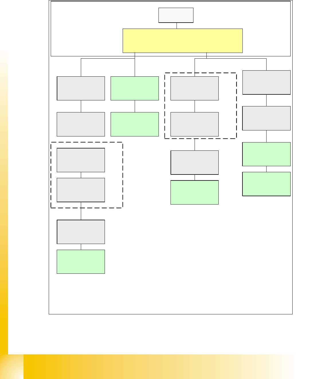
1.10.5.9 HF CAN Bus Structure With Universal Cable Harness (SW 505/Vers.2/Current)
CAN bus structure with SW 505.xx and COM assembly KSP 354; with universal cable harness
(labeling on cable = 0301xxxx-0x); one CAN bus for each placement area.
Fig. 1.10 - 21 HF CAN bus structure (one CAN bus per PA, universal cable harness, SW 505 version 2)
SMP BUS
C
O
M
U
n
i
t
K
S
P
3
5
4
MC
CAN Bus cable 2
Computer Unit
For each Placementarea one CAN Bus!
* with SW 505 Gantry 2 is changed to gantry 3
new cable loop!
new circuit diagram!
Trailing cable-
Interface
Gantry 1
Transport
COT 1
Tape cutter
Control unit
CAN Bus cable 1
CAN E/
A
Modu
l
Sektor
4
CAN E/
A
Modu
l
Sektor
4
CAN E/
A
Modu
l
Sektor
4
CAN I/O
SUB Module
Section 4
Vision
Control unit
SUB Distributor Section 4
Section 4
COT 4 / MTC
Tape cutter
Vision
Section 2
CAN I/O
Main Module
Section 2
Main Distributor Section 2
Control unit
COT 2 / MTC
Tape cutter
Axis unit
PA 2
COT 3
Tape cutter
Trailing cable-
Interface
Gantry 3*
x6pnx11pn
Head board(C500)
Gantry 1
Terminator
(120 OHM)
Head board(C500)
Gantry 3*
Terminator
(120 OHM)
Terminator (120 OHM)
[near the trailingcable
interface]
Terminator (120 OHM)
[near the trailingcable
interface]
1 - 43
Siplace CAN Test Box
Edition 04/2008 1 CAN Test Box
43
Fig. 1.10 - 22 HF CAN bus structure (one CAN bus per PA, universal cable harness, SW 505 version 2)
Vision-Steuerung
00363 961
CAN
Hauptverteiler 0301 0004 (qa)
X2qd
X2qd
Einzug 2 Einzug 1
X125X126
CAN-InCAN-Out
X115X116
CAN-InCAN-Out
CAN
LP-Steuerung
X22ao
X22ao
CAN I/O-Modul
00355 051
(qb)
Bu
StBuSt
Bu
0301 0050
CAN
0301 0051
X2rd
X145
CAN-In
BuBu
Achseinschub 2/3
0301 6110
X30_2sq
CAN
Einzug 3
X136
CAN-Out
X40ca
CAN
St
X2rd
CAN
Unterverteiler 0301 0005 (ra)
Vision-Steuerung
00363 961
Einzug 4
Schlepp Interface
0301 0612 (ca)
P3
0301 0054
Computereinschub
X135
CAN-In
Bu
Bu
X68
Umgebungsdrucksensor
Pneumatikeinheit
Bestückbereich 2
Bestückbereich 1
CAN
X30_2sq
X30_1sq
Bu
X30_1sq
Bu
X30_2tq
Bu
X30_1tq
X146
CAN-Out
St
CAN I/O-Modul
00355 051
(rb)
X40aa
Schlepp Interface
0301 0612 (aa)
P1
0301 0059
X40ca
Bu
X40ba
Bu
0301 0053
Bu
Bu
X40aa
Bu
Bu
Bu
X1rb
X1qb
0300 2110
X6pn
X6pn
Kommunikationsbaugruppe
X7pnX12pn
freifrei
X11pn
X11pn
CAN-BUS 1CAN-BUS 2
St
120 Ohm
Abschlusswiderstand
0302 7646
X1
120 Ohm
Abschlusswiderstand
0302 7646
X1
St
0301 0052
X30_1sq
Bu
frei
X2he
X1he
1-Wire Hub
0301 0577 (he)
X2he
X1he
1-Wire Hub
0301 0577 (he)
X40da
CAN
X1qb
CAN
X1rb
AderNr. Belegung Sub-D- PIN
CAN_H4
RESET
frei
PowerFail
CAN_INT
GND
8
9
6
7
5
GND
CAN_L
"1-Wire"
CAN-Bus Aderbelegung
1
3
2
7
9
5
8
4
3
1
2
6
(qd)
(rd)
Siehe Seite 4-9
Siehe Seite 5-37
Siehe Seite 5-28
Siehe Seite 3-12
Siehe Seite 5-28
Siehe Seite 5-37
Siehe Seite 3-8
Siehe Seite 4-19
Siehe Seite 5-57
Siehe Seite 5-57
1 - 44
Siplace CAN Test Box
1 CAN Test Box Edition 04/2008
44
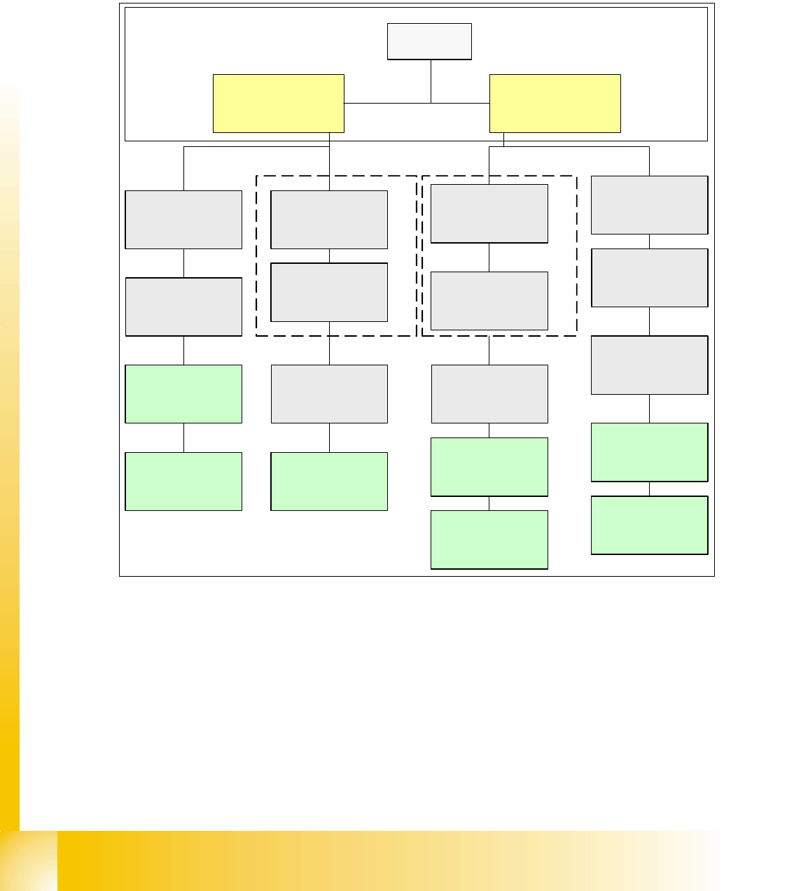
1.10.6 CAN Bus Structure for HF/3
1.10.6.1 HF/3 CAN Bus Structure With KSP352 (Current)
CAN bus structure with SW 505.xx and COM assembly KSP 352; with universal cable harness
(labeling on cable = 0301xxxx-0x); one CAN bus for each placement area.
Fig. 1.10 - 23 HF/3 CAN bus structure (one CAN bus per PA, universal cable harness, SW 505 with KSP352)
SMP BUS
C
O
M
U
n
i
t
K
S
P
3
5
2
(
r
i
g
h
t
)
MC
CAN Bus cable 2
Computer Unit
Trailing cable-
Interface
Gantry 4
Transport
COT 1
Tape cutter
Control unit
CAN Bus cable 1
CAN E/
A
Modu
l
Sektor
4
CAN E/
A
Modu
l
Sektor
4
CAN E/
A
Modu
l
Sektor
4
CAN I/O
SUB Module
Section 4
Vision
Control unit
SUB Distributor Section 4
Section 4
COT 4
Tape cutter
Vision
Section 2
CAN I/O
Main Module
Section 2
Main Distributor Section 2
Control unit
COT 2 / MTC
Tape cutter
Axis unit
PA 2
COT 3
Tape cutter
Trailing cable-
Interface
Gantry 3
x6po
Head board(C500)
Gantry 1
Terminator
(120 OHM)
Head board(C500)
Gantry 3
Terminator
(120 OHM)
Terminator (120 OHM)
[near the trailingcable
interface]
Axis unit
PA 1
Head board(C500)
Gantry 4
Terminator
(120 OHM)
Trailing cable-
Interface
Gantry 1
C
O
M
U
n
i
t
K
S
P
3
5
2
(
l
e
f
t
)
x6pn