CAN Bus Workshop_Version 03__06-2008_EN.pdf - 第57页
1 - 31 S tudent Guide CAN BUS W orkshop Edition 0 6 /2008 2 Comm unication and Control 31 2.2.1 1 Communikation C&P 20 Head The TQM –modu el on the head inte rface C500 is commun icate via the CAN Bus (1M/B aud) to t…
1 - 30
Student Guide CAN BUS Workshop
2 Communication and Control Edition 06/2008
30
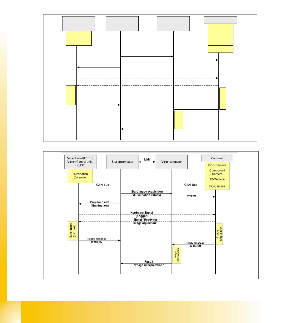
2.2.10.1 Communication during a image acquisition
The main communication between the vision system and machinecontroller is the transmission of
illumination values. These values, stored in the GF, are sent via CAN bus to the camera in ques-
tion. As soon as the camera should take the picture, the camera illumination is activated by a trig-
ger. From this moment on the row of LEDs which provide the different illumination levels light
dependant on the illumination value 0-255. This illumination value can have 0 = dark up to 255 =
bright. All illumination levels start lighting at the same moment. The value 0-255 determines the
length of the illumination time.The maximum length of illumination is limited to 6 ms.
Fig. 2.2 - 22 Time sequence from up to down for the Communication Image acquisition with SW60x
Fig. 2.2 - 23 Time sequence from up to down for the Communication Image acquisition with SW70x
Cameras
Illumination
Controller
Machine controller
(MC)
Stationcomputer with
Visionsoftware
Prepare
CAN Bus
Illumination
(ca. 6ms)
PCB-Camera
FC-Camera
IC-Camera
Component
Camera
Start Image acquisition
(Illumination values)
Prepare Flash
(illumination)
Hardware Signal
(Trigger)
Visionboard(LP,BE)
Vision Control unit ,
(IC,FC)
Ready message
to the MC
Signal "Ready for
Image aquisition"
CAN Bus
Image
interpretation
Image
acquisition
Ready message
to the VISION SW
Result
"Image interpretation"
1 - 31
Student Guide CAN BUS Workshop
Edition 06/2008 2 Communication and Control
31
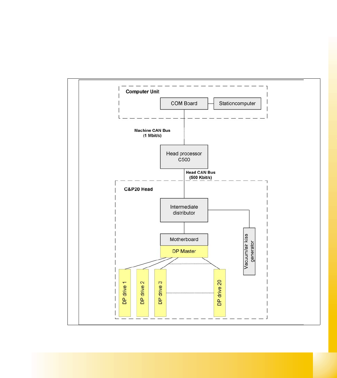
2.2.11 Communikation C&P 20 Head
The TQM –moduel on the head interface C500 is communicate via the CAN Bus (1M/Baud) to the
Machine controller.
The communication from the head interface to the C&P20 head is carried out with an additional
CAN Bus. Which send the data with 500KBaud.
The 20 DP - axes are controled via the „DP- Master" on the motherboard. So the machine CAN
Bus send 4 commands:
– Start the DP axis after Pick up/Placement (Pick up angle/Placement angle)
– Start the DP axis after Vision (Correction angle)
– Wait DP axis before Vision (Position commando not allowed)
– Wait DP axis before Pick up/Placement (Position commando not allowed)
Fig. 2.2 - 24 CAN-Bus controlled head function on the C&P 20 head
1 - 32
Student Guide CAN BUS Workshop
2 Communication and Control Edition 06/2008
32
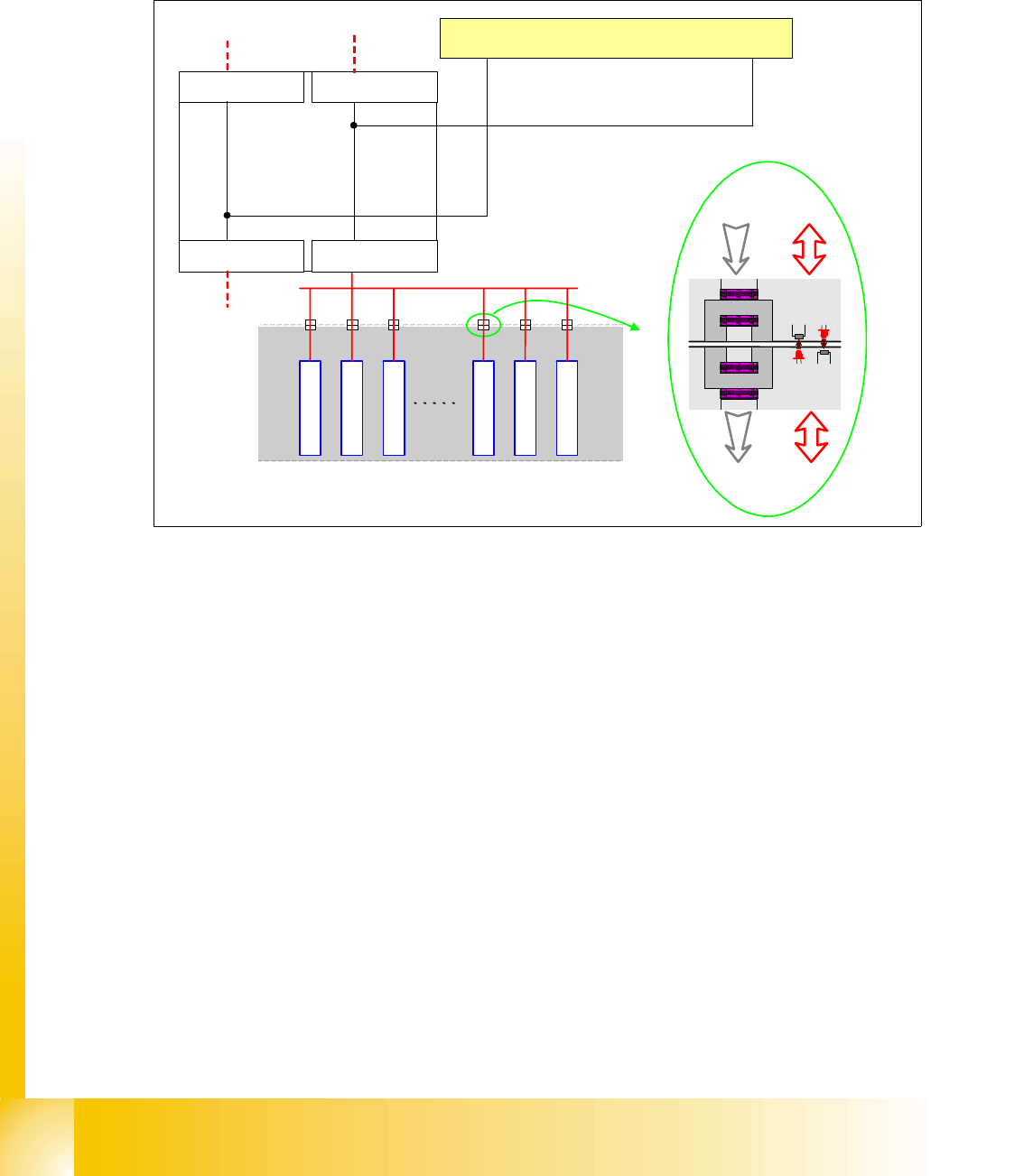
2.2.12 Communication X-Feeder
The Communication between the Feeder Control unit (FCU) and each X- Feeder is carried out via
a CAN bus. This CAN bus is only responsible for the communication between FCU and X-Feeder
and machines CAN bus controlled the "Feeder Can Bus". The data and power supply from the
FCU to each feeder is contactless.
Fig. 2.2 - 25 Communication X-Feeder
2.2.12.1 Tape Cutter and Nozzle Changer - Communication
Description of CAN node NC tape cutter module 2
The introduction of the SIPLACE X4I and the further development of the SIPLACE X series also
brings with it the integration of the nozzle changer control and the monitoring sensors into the
machine CAN bus. This new board is named "CAN node NC tape cutter module" [03052927-xx]
and is used in place of the former tape cutter board. This board contains the control system for
the tape cutter unit, NC 1 & 2, nozzle station (blast air valve for C&P20 head) and sensors for the
component/nozzles reject bin. The firmware for the CAN nodes is loaded onto the tape cutter
board with the help of the station software or CACCIA. The "CAN node NC tape cutter" is
backwards compatible with the old tape cutter boards. This assembly can therefore be used in X,
HF and D series machines.
SIPLACE
X-Serie
Feeder
Feeder
Feeder
Feeder
Feeder
Feeder
Feeder-CAN Bus
BE-Wagen
(COT)
Power Data
Power Data
Machine CAN Bus
FCU Location 1
C
O
M
U
n
i
t
x
6
p
n
x
7
p
n
FCU Location 2
FCU Location 3FCU Location 4