CAN Bus Workshop_Version 03__06-2008_EN.pdf - 第163页
CACCIA Manual 1 Caccia Student Guide Issue 04/2007 EN 71 Affected R ange 1 This is where you can define the ad dress range for which a trace is to be recorded: 1 1 1 Decode 1 Set a tick at Decode if you want to display t…
1 Caccia Student Guide CACCIA Manual
Issue 04/2007 EN
70
1
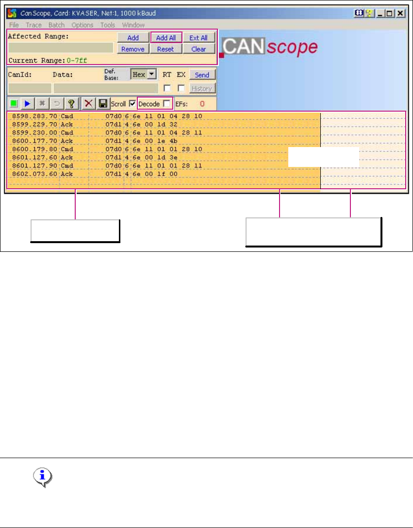
Fig. 1 - 46 CanScope dialog box
→ In the CanScope (Net 1 and Net 2) dialog boxes, click on the Add All button to record the com-
munication protocols of all CAN telegrams.
→ To start the recording, select Trace - Start Trace from the menu. The write file to dialog box
will open. Select the name and path of the file in which the trace is to be stored.
→ Switch on the machine and the communication to the subsystems will be loaded via the rele-
vant CAN command.
The recording will start. You can see this by the orange color of the recording field. If no record-
ing is being performed, the field will be light beige. 1
The contents of the recording field will be stored in the specified file. 1
→ To stop the recording, select Trace - Stop Trace from the menu.
Note
With the help of the trace data, the developer can detect which subsystem has not reported itself.
The error message explains where the problem is located. 1
1
Trace
inactiveactive
Tracing field
Left (orange ): Trace active
Right (brown): No Trace

CACCIA Manual 1 Caccia Student Guide
Issue 04/2007 EN
71
Affected Range 1
This is where you can define the address range for which a trace is to be recorded: 1
1
1
Decode 1
Set a tick at Decode if you want to display the figures in the right column of the recording field in
short clear text passages. 1
Note
This option is not suitable for remote diagnosis by R&D. 1
→ Complete the recording by selecting Trace - Stop Trace from the menu. The recording field
will return to beige.
→ When you leave the CanScope dialog box, the file last chosen will remain as the prompt value
for the next time.
1
Example:
Contents of file: CAN control window Net 1 @11_03_2005_16_56_08.txt
(This file name is assigned automatically.) 1
T: 257122.779.20 CanId: 07d0 L: 6 Data: 6e 11 01 04 28 10
T: 257122.779.60 CanId: 07d1 L: 4 Data: 6e 00 1d 32
T: 257123.725.50 CanId: 07d0 L: 6 Data: 6e 11 01 04 28 11
T: 257123.725.80 CanId: 07d1 L: 4 Data: 6e 00 1e 4b
T: 257124.671.40 CanId: 07d0 L: 6 Data: 6e 11 01 01 28 10
1
Add All
Records the communication protocols for all CAN telegrams.
Note The evaluation may be extensive if this option is chosen.

1 Caccia Student Guide CACCIA Manual
Issue 04/2007 EN
72
1.11 One Wire Bus
The introduction of the message loop in software version 505 (601) made it necessary to either
reduce the number of inputs/outputs or to install an additional I/O module. In order to save space
and minimize costs, we decided to introduce the "one wire bus system".
The one wire bus controls the nozzle changer in all 4 sectors, transmits the temperature values
from the sensors at the head boards and reads out the gantry data.
Tasks:
(1) Control the Nozzle changer 6/12 C&P heads (1st and 2nd row).
2. Control the Nozzle changer 20 C&P heads (1st and 2nd row), with magazine monitoring
(3) 2 Temperature sensors per gantry, fixed to the head plate.
(4) Storage of gantry identification on an EEPROM.
(A differentiation is made between Plate gantry CFK-02, D
esign To Cost (DTC) gantry CFK-04
and CFK 06 gantry. This means that the machine database loaded for the dynamic parameters
of the main axis differs according to the gantry type concerned).
5. Option: Monitoring of the reject box
1.11.1 One Wire Bus - Structure
As the name indicates, the data are transferred (serial transfer) via a single wire, to the relevant
subsystem.
The one wire bus system is used for processes where time is not a critical factor and can be real-
ized as a single master bus with „any number“ of slaves (stations).