CAN Bus Workshop_Version 03__06-2008_EN.pdf - 第218页
1 - 10 Siplace C AN T est Box 1 CAN T est Box Edition 04/200 8 10 Step by step: 1 ➠ Connec t the CA N T est Box to the se rvice plug (Not e: Not al l si gnals on the S ervice pl ug) of the COM assemb ly . ➠ Connec t the …
1 - 9
Siplace CAN Test Box
Edition 04/2008 1 CAN Test Box
9
1.7 Checking the CAN Bus Voltage Level
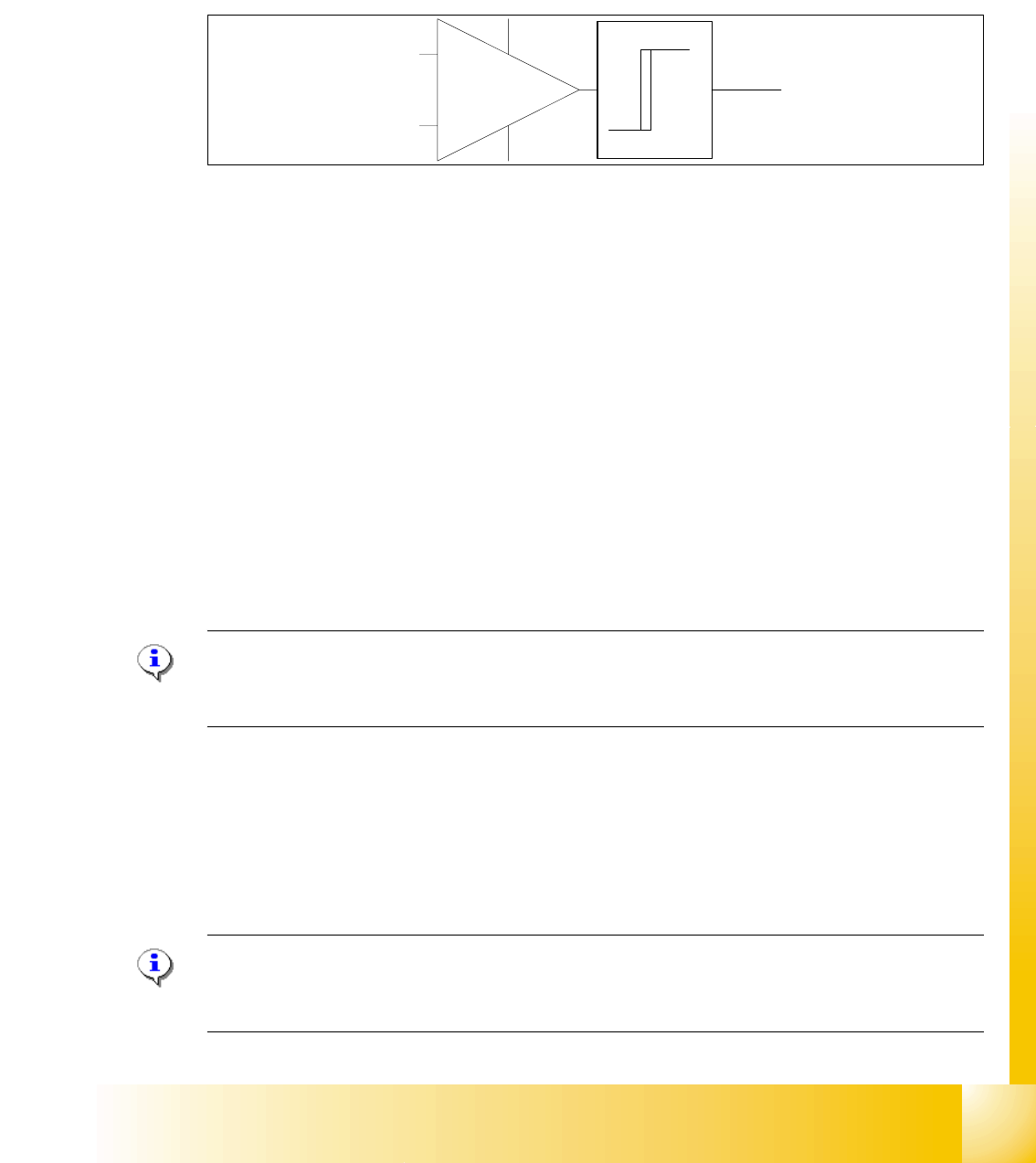
The CAN levels for CAN_H and CAN_ L differentiate between recessive and dominant levels. This
two levels will convert into a TTL level, for the CAN Processor. The RxD Signal has the same
phase such as the CAN_L Signal.
Abb. 1.7 - 1 RxD signal
1.7.1 Checking the Recessive Level
The recessive level (when CAN bus is idle i.e. there is no data transmission) can be measured
statically, with a voltammeter. Make sure no telegrams are sent during the measurement proce-
dure. This means that measurement may only be performed when the machine is not in operation.
Step by step: 1
➠ Connect the CAN Test Box to the service plug (Note: Not all signals on the Service plug) of the
COM assembly.
➠ Switch the machine on and wait until it has booted.
➠ Measure the voltage level at the banana sockets between CAN H and GND or between CAN
L and GND, with the help of a measuring device.
➠ You should receive a voltage value of 2.5 V +/- 0.3 V for CAN_H and CAN_L.
Note: If you discover a short circuit or incorrect voltage level, disconnect the subsystems from
the CAN bus, one after the other. For suitable disconnection points, please refer to the circuit di-
agrams.
1.7.2 Checking the Dominant Level
The dominant CAN H and CAN L levels contain the information and need to reach a certain volt-
age level. These two CAN signals form a TTL CAN (RxD) signal, which can then be interpreted
by the CAN processor.
Note: You need an oscilloscope to measure the dominant level.To minimize the extent to which
the measurement system influences the CAN signals, keep the measurement line as short as pos-
sible.
CAN_L
CAN_H
RxD
TTL Pegel
(Level)
1 - 10
Siplace CAN Test Box
1 CAN Test Box Edition 04/2008
10
Step by step: 1
➠ Connect the CAN Test Box to the service plug (Note: Not all signals on the Service plug) of the
COM assembly.
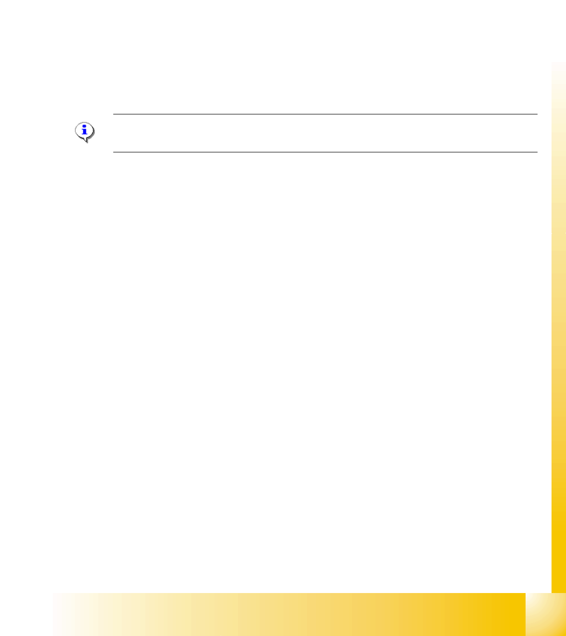
➠ Connect the oscilloscope to the BNC sockets CAN_H and CAN_L.
➠ Set the measurement range for channels 1 and 2 to 1V and the sweep to 2μs
(see Fig. 1.7 - 3) and the trigger to channel 1.
➠ Switch the machine on and wait until it has booted.
➠ When the machine is in idle mode, position the signals on the oscilloscope into the center of
the screen.
➠ To simulate CAN bus communication, you can start a version query in Sitest or Caccia.
➠ Press the Stop button on the oscilloscope.
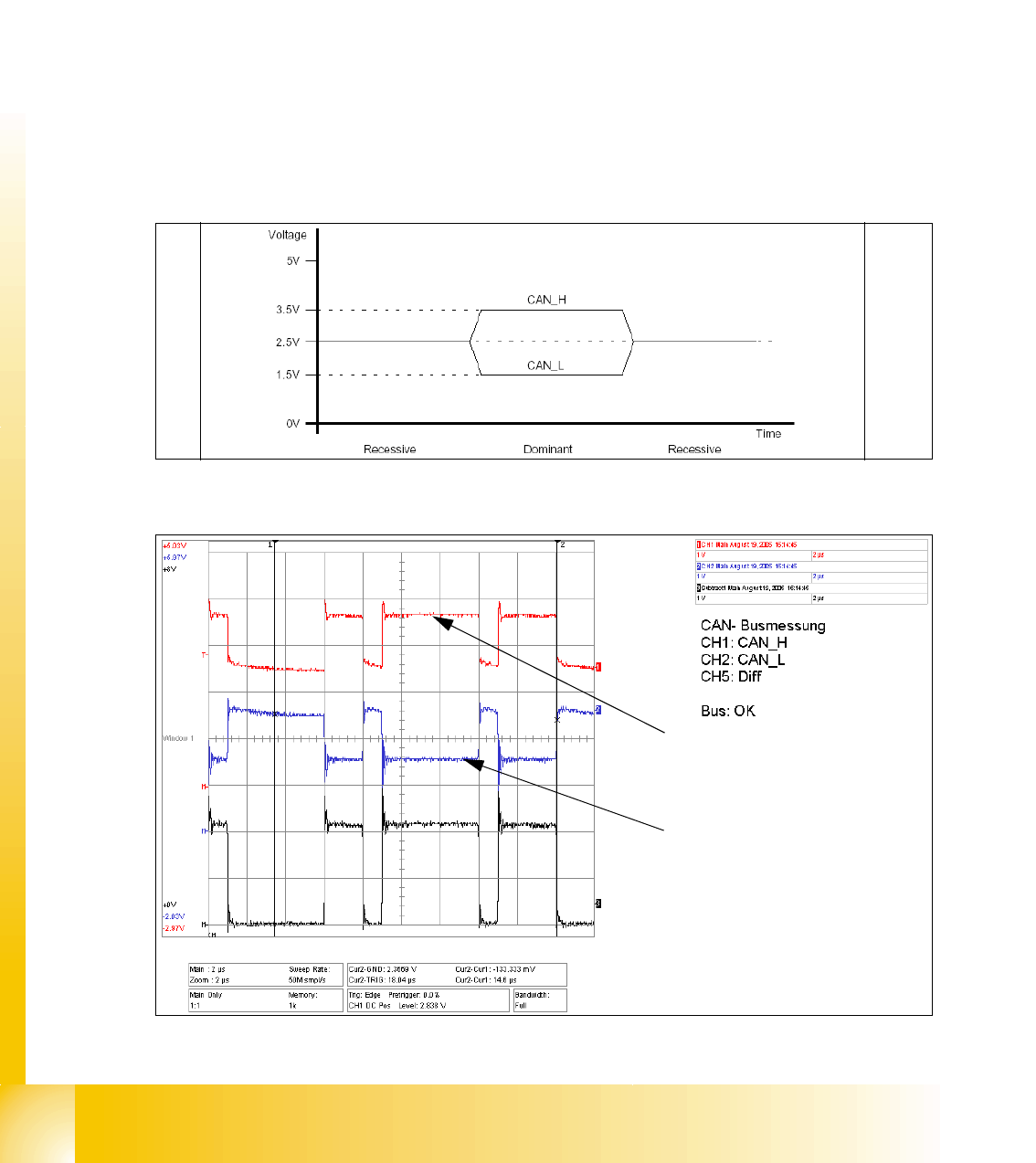
➠ You can now check the signal voltage levels. You should receive a value of 3.5V ( 2.75 - 4.5V)
for CAN_H and of 1.5V (2.0 - 1.0V) for CAN_L .
Fig. 1.7 - 2 Theoretical representation of recessive and dominant CAN_H and CAN_L signals
Fig. 1.7 - 3 Recessive and dominant CAN_H and CAN_L signal
Dominant CAN_H signal
Dominant CAN_L signal
1 - 11
Siplace CAN Test Box
Edition 04/2008 1 CAN Test Box
11
1.8 Checking the CAN Bus for Error Frames
What are error frames?
Error frames are sent by the individual subsystems, when a command does not adhere to the en-
coding rules or has been physically corrupted.
This occurs when a CAN telegram shows the same RxD level (low) for 6 or more consecutive bits
(logic 0 = dominant).
If a subsystem recognizes this type of command, it will immediately notify all other subsystems
and the transmitter of the telegram, by sending error frames.
After receiving an error frame, the other subsystems will reject the message (telegram) sent and
send their own error frames. Once the bus is free again, the command will be resent.
The CAN Test Box is used to check the CAN network for error frames.
Note: When switching the machine on and off, the CAN Test Box will recognize any error frames.
This means that the Error Frame Counter have to reset after each reboot manually.
Step by step: 1
➠ Connect the CAN Test Box to the service plug (Note: Not all signals on the Service plug) of the
COM assembly.
➠ Switch the machine on and start the placement program.
➠ During production, the CAN Test Box can remain connected, even with the oscilloscope. The
trigger input should be connected to the BNC socket error frame of the CAN Test Box.
➠ The number of error frames can be seen on the counter. An accumulation of error frames in-
dicates possible physical bus errors.
If too many error frames are recognized during operation, you will need to analyze the CAN
signals in detail.
Guideline value: Number of error frames during 4h placement operation < 10