CAN Bus Workshop_Version 03__06-2008_EN.pdf - 第145页
CACCIA Manual 1 Caccia Student Guide Issue 04/2007 EN 53 1.6.6 T win Head → Click on the button to open the Subsystem Co ntrol Center d ialog box: 1 Fig. 1 - 29 T w in head 1.6.7 Boot strap Loader A364 1.6.7.1 In General…
1 Caccia Student Guide CACCIA Manual
Issue 04/2007 EN
52
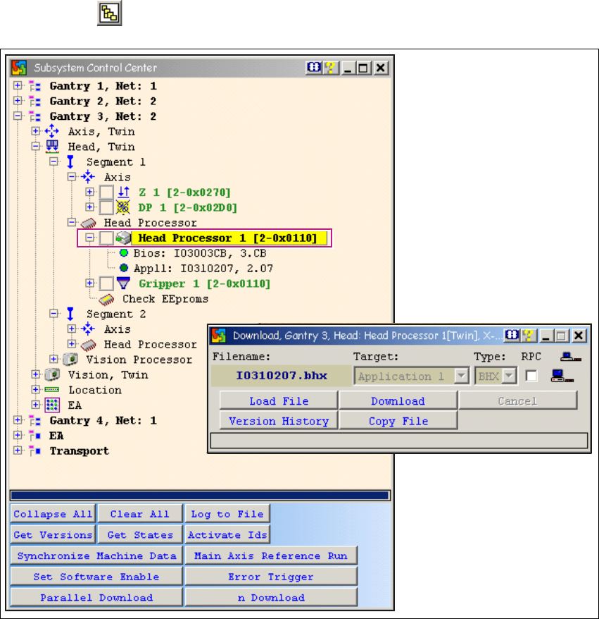
1.6.5 Twin Head Firmware Download
→ Click on the button to open the Subsystem Control Center dialog box:
1
Fig. 1 - 28 Twin head firmware download
For X or HF series machines:
Determine whether the selected machine operates with a twin head or with one or two TQM mod-
ule processors. Only select one segment for the download. The same applies when using SITEST.1
When performing a firmware (eSW) download, only select one segment (1 or 2) and then continue
the download as usual. 1
If both segments are selected, you will not be able to perform the download with a firmware i.e.
the 2nd address can not be addressed. 1
1
CACCIA Manual 1 Caccia Student Guide
Issue 04/2007 EN
53
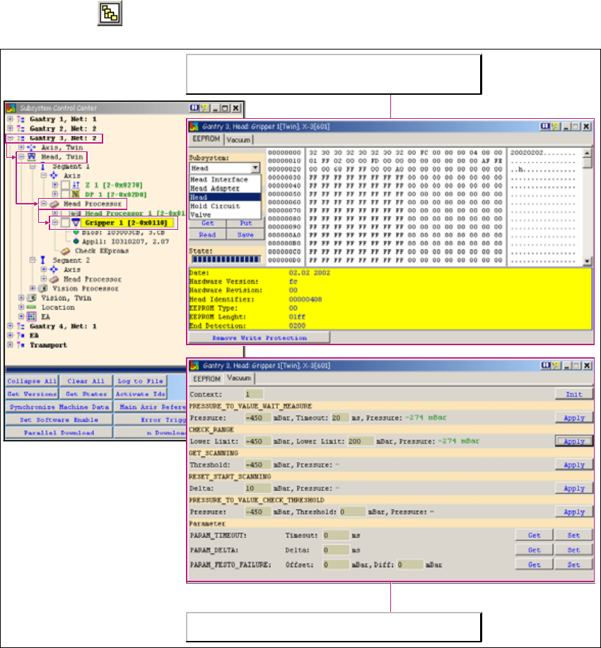
1.6.6 Twin Head
→ Click on the button to open the Subsystem Control Center dialog box:
1
Fig. 1 - 29 Twin head
1.6.7 Bootstrap Loader A364
1.6.7.1 In General
Also for the new axis card A364 it is possible to execute a BIOS download via V24 interface
(R232) - just as for the former axis cards A362 and A362.
Contrary to the former version the program Bootstrap Loader is integrated in CACCIA and by
means of the adapter card a download can be executed.
CACCIA can be used to record the vacuum values at both TWIN
head segments.
The two TWIN head segments are controlled by the head processor
on the head board. The EPROM query for the 16-bit processor is
also initiated here.
1 Caccia Student Guide CACCIA Manual
Issue 04/2007 EN
54
1.6.7.2 Requirements:
– A service laptop with CACCIA version 14.0.97 or higher.
– Adaptercard for A364 [3051220-02] or a special adapter card for A362/A363/A364
– Serial cable e.g. CAN bus testing cable [00349679-03]
– Current BIOS version on the service-laptop or on memory stick
1.6.7.3 BIOS Download via V24-Interface
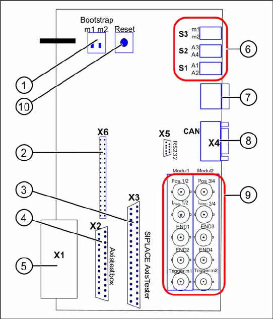
Adapter card for A364
Fig. 1 - 30 Adapter card for axis card A364
Functional Principle:
The axis controller card A364 works with 2
processors, which control 4 Axis of a
placement machine.
Key
1. Switch for Bootstrap-Download to the
processors m1/m2
2. Diagnostics connector (unused / not
connected)
3. Connection for SIPLACE Axis Tester
4. Connection for Axis test box
5. V24 Interface (RS232)
connection for BIOS download via
Bootstrap Loader
6. S3 Switch for 7-segment display for
processor m1 or m2 S2 Switch for axis
dynamic signals A3 or A4 of processor m2
(at right BNC-connectors) S1 Switch for
axis dynamic signals A1 or A2 of processor
m1 (at left BNC-connectors)
7. Diagnostics display for the processors m1
resp. m2
8. CAN-Bus connector (9pole Sub-D)
9. BNC connections for the axis signals
10. Reset switch for both processors