CAN Bus Workshop_Version 03__06-2008_EN.pdf - 第23页
1 - 15 S tudent Guide CAN BUS W orkshop Edition 06/2 008 1 Operat ional safety 15 Fig. 1.3 - 4 Safety circuits Start button pressed Compressed air min. 0.5 MPa (5.0 bar)? No Emerg. stop push-button pressed? Protective co…

1 - 14
Student Guide CAN BUS Workshop
1 Operational safety Edition 06/2008
14
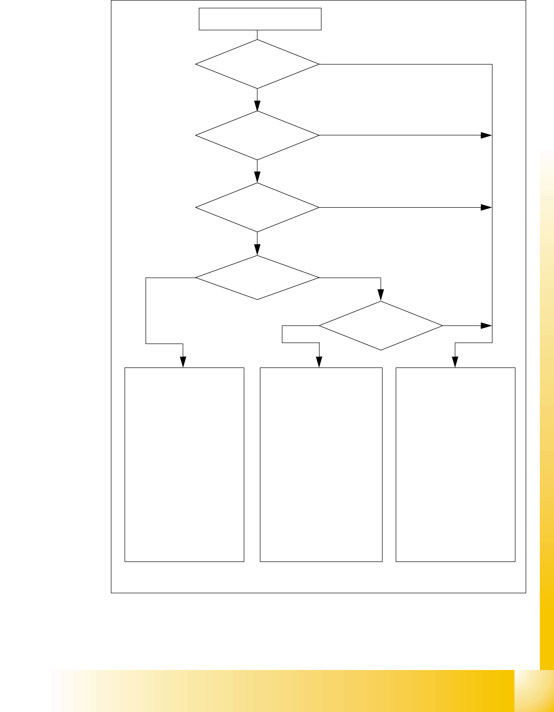
1.3.3 Safety circuit and signaling circuit
1.3.3.1 Description of the functions of the safety circuit
The following conditions must be fulfilled in order to start and operate the placement machine:
– all four component trolleys must be docked in and connected.
– all covers - four over the gantries, one over the PCB input belt and one over the output belt -
must be closed.
– both emergency stop push-buttons must be released.
– the cover flaps (option) over the feeders must be closed.
– the minimum operating pressure must have been reached.
– the "software enable" signal must be active. This ensures that the safety circuit is closed.
– the power supply must be sending 24 V to the Start buttons and the protective contactor com-
bination.
– If one of the Start buttons is now pressed, the protective contactor combination PCC K6 will
switch and activate the following components:
– 250 VDC link voltage for the servo amplifiers for the gantry axes
– 145 VDC link voltage for the star axes
– the axis unit receives a "Servo Enable" signal for the servo amplifier
– 34 VDC operating voltage is switched to the component trolleys.
– 24 VDC operating voltage is switched to the used tape cutters.
– the PCB conveyor control receives the enable signal for the PCB clamping, the PCB stop-
per and the lifting table control.
The machine is then ready for use.
1 - 15
Student Guide CAN BUS Workshop
Edition 06/2008 1 Operational safety
15
Fig. 1.3 - 4 Safety circuits
Start button pressed
Compressed air
min. 0.5 MPa
(5.0 bar)?
No
Emerg. stop
push-button pressed?
Protective cover open ?
Safety mode
activated on the user
interface?
No
Component
trolley safety circuit
interrupted?
Yes
No
No
Yes
Yes
No
Active
PCC*) Yes
Voltage
Y axis 250 V-
X axis 250 V-
star axis 145 V-
DP axis/D-Twin 40 V-
Z axis/Z-Twin 40 V-
Active
PCB conveyor Yes
Lifting table Yes
PCB clamping Yes
Width adjustment Yes
Laser light barrier Yes
Tape cutter Yes
CO trolley dock. unit Yes
Yes
Active
PCC*) No
Voltage
Y axis 0 V
X axis 0 V
star axis 0 V-
DP axis/D-Twin 40 V-
Z axis/Z-Twin 40 V-
Active
PCB conveyor Yes
Lifting table No
PCB clamping No
Width adjustment Yes
Laser light barrier No
Tape cutter No
CO trolley dock. unit Yes
Active
PCC*) No
Voltage
Y axis 0 V
X axis 0 V
star axis 0 V-
DP axis/D-Twin 40 V-
Z axis/Z-Twin 40 V-
Active
PCB conveyor No
Lifting table No
PCB clamping No
Width adjustment No
Laser light barrier No
Tape cutter No
CO trolley dock. unit No
*) PCC protective contactor combination K6
Yes
Start button pressed

1 - 16
Student Guide CAN BUS Workshop
1 Operational safety Edition 06/2008
16
1.4 ESD guidelines
1.4.1 Handling ESD modules
Do not touch electronic modules unless it is absolutely essential to do so in order to carry out other
work. If it is necessary, make sure that you do not touch the pins or printed conductors when you
pick up flat modules.
Do not touch components unless
➠ you are constantly earthed by an ESD wrist strap or
➠ you are wearing ESD shoes or ESD shoe earthing strips on an ESD floor.
Always discharge yourself before you touch an electronic module. To do this, simply touch a con-
ductive and earthed object immediately before you touch the module (such as unpainted parts of
a switch cabinet, a water pipe, etc.).
Do not allow modules with chargeable and highly insulating materials to touch one another, e.g.
plastic films, insulating table surfaces or items of clothing made from synthetic fibers.
Always place the modules on a conductive surface (table with an ESD coating, conductive ESD
foam, ESD bag or container).
Do not bring modules near visual display units, monitors or televisions. Keep them at least 10 cm
away from the screen.
1.4.2 Measurements and modifications to ESD modules
Do not take measurements on such modules unless
– the measuring device is earthed (e.g. via PE conductors) or
– you discharge the measuring head just before taking measurements with a potential-free mea-
suring device (e.g. by touching an unpainted metal part of the controller casing).
➠ Always use an earthed soldering iron if you carry out any soldering work.
1.4.3 Dispatching ESD modules
➠ Always store modules and components in conductive packaging (e.g. metallized plastic bags
or metal sleeves) and dispatch them in conductive packaging.
If the packaging is not conductive, place the modules in a conductive envelope before packag-
ing. (Use ESD bags, domestic aluminum foil or paper, for example. NEVER use plastic bags
or film). 1
➠ If the module has integral batteries, ensure that the conductive packaging does not touch or
short-circuit the battery terminals and, if necessary, first cover the terminals with insulating tape
or material.