CAN Bus Workshop_Version 03__06-2008_EN.pdf - 第165页
CACCIA Manual 1 Caccia Student Guide Issue 04/2007 EN 73 1.1 1.1.1 Basic S tructure The one wire bus system consists in principle of a master with EEPR OM (control un it), which con- trols the various submodules such as …

1 Caccia Student Guide CACCIA Manual
Issue 04/2007 EN
72
1.11 One Wire Bus
The introduction of the message loop in software version 505 (601) made it necessary to either
reduce the number of inputs/outputs or to install an additional I/O module. In order to save space
and minimize costs, we decided to introduce the "one wire bus system".
The one wire bus controls the nozzle changer in all 4 sectors, transmits the temperature values
from the sensors at the head boards and reads out the gantry data.
Tasks:
(1) Control the Nozzle changer 6/12 C&P heads (1st and 2nd row).
2. Control the Nozzle changer 20 C&P heads (1st and 2nd row), with magazine monitoring
(3) 2 Temperature sensors per gantry, fixed to the head plate.
(4) Storage of gantry identification on an EEPROM.
(A differentiation is made between Plate gantry CFK-02, D
esign To Cost (DTC) gantry CFK-04
and CFK 06 gantry. This means that the machine database loaded for the dynamic parameters
of the main axis differs according to the gantry type concerned).
5. Option: Monitoring of the reject box
1.11.1 One Wire Bus - Structure
As the name indicates, the data are transferred (serial transfer) via a single wire, to the relevant
subsystem.
The one wire bus system is used for processes where time is not a critical factor and can be real-
ized as a single master bus with „any number“ of slaves (stations).

CACCIA Manual 1 Caccia Student Guide
Issue 04/2007 EN
73
1.11.1.1 Basic Structure
The one wire bus system consists in principle of a master with EEPROM (control unit), which con-
trols the various submodules such as A/D converters, EEPROM, temperature and I/O modules.
Each communication branch is equipped with an upstream coupler, which opens the branch for
data transfer.
Fig. 1 - 47 One wire bus principle
Slave
Master
Coupler
E²
A/D A/DA/D I/O
Coupler
E²
°C I/O°C
E²
Slave
1 Caccia Student Guide CACCIA Manual
Issue 04/2007 EN
74
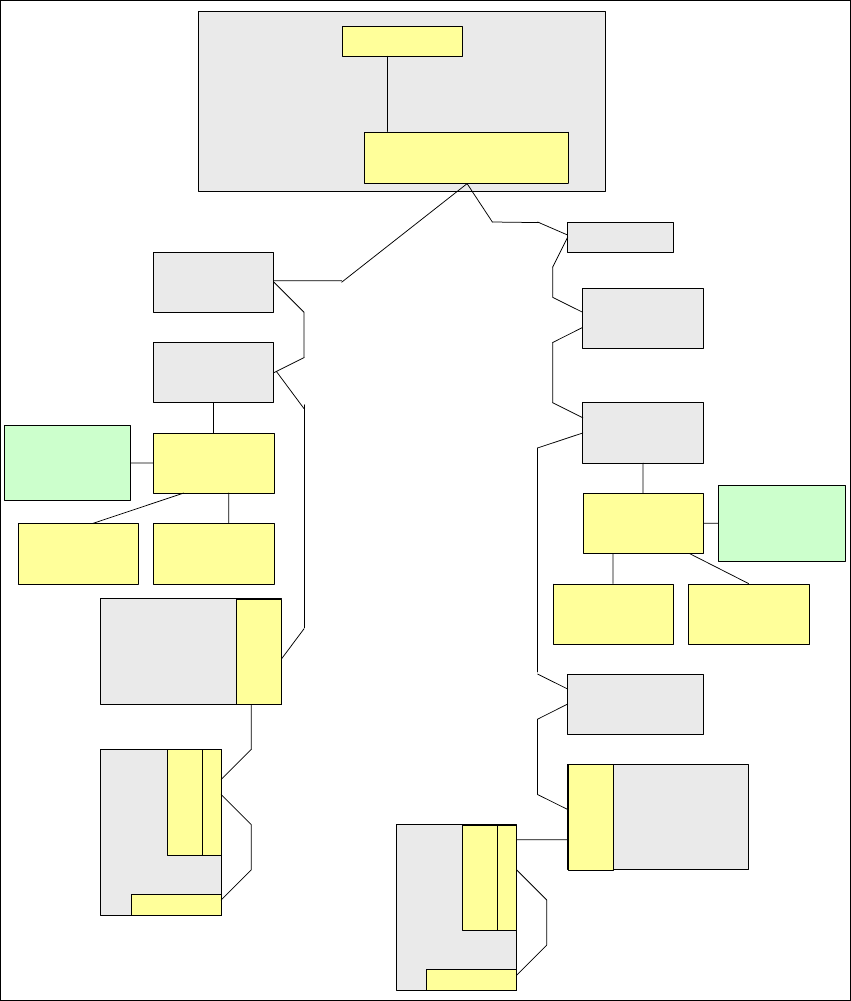
1.11.1.2 One Wire Bus in the HF Machines
The one wire bus in integrated into the machine CAN bus cable and therefore divided into place-
ment areas 1 and 2. The structure or arrangement of the CAN stations is identical with that of the
machine CAN bus. Pin 1 (wire 1) of the machine CAN bus is used for the one wire system.
Fig. 1 - 48 Overview of one wire subsystems e.g. BB1 on the HF machine
Vision
Control unit
Sector 4
Conveyor
Control
Axis unit
BB 1
Option: Check reject bin
or terminating plug
Attention: no CAN-
termination resistor
COM Board
I/O SUB Module
Sector 4
One Wire Bridge
(driver)
Nozzle Changer
Hub (Coupler)
Temp.sensor
CO-Table 4
Cutter
Head
plate
Control Board
NC (C&P20)
Row 1
Control Board
NC (C&P20)
Row 2
Trailing Unit Interface
Gantry 4
1 Wire Board
(Trailing Unit
Interface)
Temp.sensor
Nozzle Changer
Hub (Coupler)
CO-Table 1
Cutter
Control Board
NC (C&P20)
Row 1
Control Board
NC (C&P20)
Row 2
Trailing Unit Interface
Gantry 1
1 Wire Board
(Trailing Unit
Interface)
Temp.sensor
Head
plate
Temp.sensor
Gantry
recognition
Option: Check reject bin
or terminating plug
Attention: no CAN-
termination resistor
TQM Module
(Master)
RS232
Machine CAN Bus with
One Wire
Gantry
recognition